- Build Your Smart Temperature-Controlled Switch Circuit
- Energy Leak Detection Circuit: Build Your 20°C Thermistor Detector
- Build Your Precise Heating System Thermostat Circuit
- Fridge Open Alarm Circuit: Build Your Smart Protection System
- Fridge Door Alarm Circuit: Robust Design for 1.3V Operation
- Build Your Fridge Door Alarm Circuit – 20 Second Alerts
- Build Your Fire Alarm: Thermistor Circuit Diagram (10K)
- Build Your 3-Degree Thermostat Circuit with LM339
- Temperature Monitor Circuit Diagram: 2-Channel Alarm Design
- Build Your Precise 12V Heating System Thermostat Circuit
- Build Your Fridge Door Alarm: 20-Second Timer Circuit
- Build Your 15k-45k Temperature Alarm Circuit
- Temperature-Controlled Fan Circuit Diagram – Build Your Smart System!
- Temperature Control Circuit: 10uV Precision & 140°C Limits
- Build Your Hot Water Level Indicator Circuit
Build Your Fridge Door Alarm: 20-Second Timer Circuit
An audible alert is triggered if the door remains open for over 20 seconds.
Operation using a 3V battery, straightforward design.
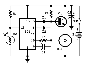
Circuit Diagram:
Components:
- R1 10K 1/4W Resistor
- R2 Photocell (any variety)
- R3, R4 100K 1/4W Resistors
- C1 10nF 63V Polyester Capacitor
- C2 100µF 25V Electrolytic Capacitor
- D1, D2 1N4148 75V 150mA Diodes
- IC1 4060 14-stage ripple counter and oscillator IC
- Q1 BC337 45V 800mA NPN Transistor
- BZ1 Piezo sounder (incorporating a 3KHz oscillator)
- SW1 Miniature SPST slide Switch
- B1 3V Battery (two 1.5V cells connected in series)
Circuit Operation:
This circuit, housed within a small enclosure, is situated within the refrigerator alongside the illumination (if available) or the access point. When the refrigerator door is sealed, the interior is shadowed, resulting in a high resistance (>200K) exhibited by the photoresistor R2, thereby maintaining pin 12 of IC1 at a high level. Upon entry of a light beam from the opening or activation of the refrigerator lamp, the photoresistor's resistance decreases (<2K), causing pin 12 to drop, and IC1 commences counting. Following a predetermined delay (20 seconds in this case), the piezo sounder emits a beep for 20 seconds, then pauses for the identical period, and the cycle repeats until the refrigerator door is closed. D2, connected to pin 6 of IC1, ensures the piezo sounder generates a frequency of 3 times per second.
Integrated Circuit Description: IC1 4060
The 4060 is a widely utilized 14-stage ripple counter and oscillator IC. This integrated circuit functions as a precise timekeeping device, generating accurate delays and oscillations. Its core functionality lies in counting pulses to produce a specific delay duration, making it ideal for applications like timer circuits, frequency generation, and signal processing. It’s known for its stability and reliability, contributing to the overall performance of this circuit.
Notes:
- Modifying D1’s connection to pin 2 of IC1 shortens the delay duration.
- The delay duration can be altered by adjusting the values of C1 and/or R3.
- Any photoresistor type can be used effectively.
- The current draw is negligible; therefore, SW1 can be omitted.
- Position the circuit near the illumination source and remove it during defrosting to prevent circuit damage due to excessive moisture.
- Avoid placement within the freezer compartment.
circuit from http://www.redcircuits.com/
