- Build Your Smart Temperature-Controlled Switch Circuit
- Energy Leak Detection Circuit: Build Your 20°C Thermistor Detector
- Build Your Precise Heating System Thermostat Circuit
- Fridge Open Alarm Circuit: Build Your Smart Protection System
- Fridge Door Alarm Circuit: Robust Design for 1.3V Operation
- Build Your Fridge Door Alarm Circuit – 20 Second Alerts
- Build Your Fire Alarm: Thermistor Circuit Diagram (10K)
- Build Your 3-Degree Thermostat Circuit with LM339
- Temperature Monitor Circuit Diagram: 2-Channel Alarm Design
- Build Your Precise 12V Heating System Thermostat Circuit
- Build Your Fridge Door Alarm: 20-Second Timer Circuit
- Build Your 15k-45k Temperature Alarm Circuit
- Temperature-Controlled Fan Circuit Diagram – Build Your Smart System!
- Temperature Control Circuit: 10uV Precision & 140°C Limits
- Build Your Hot Water Level Indicator Circuit
Temperature-Controlled Fan Circuit Diagram – Build Your Smart System!
The speed gradually increases as the temperature rises
A broadly adjustable temperature range is available
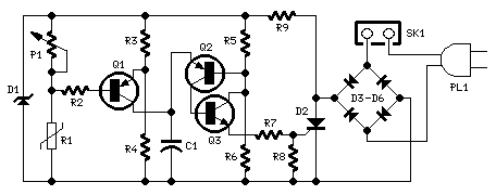
Circuit Diagram
Components:
- P1 22K Linear Potentiometer (See Notes)
- R1 15K @ 20°C n.t.c. Thermistor (See Notes)
- R2 100K 1/4W Resistor
- R3, R6 10K 1/4W Resistors
- R4, R5 22K 1/4W Resistors
- R7 100R 1/4W Resistor
- R8 470R 1/4W Resistor
- R9 33K 4W Resistor
- C1 10nF 63V Polyester Capacitor
- D1 BZX79C18 18V 500mW Zener Diode
- D2 TIC106D 400V 5A SCR
- D3-D6 1N4007 1000V 1A Diodes
- Q1, Q2 BC327 45V 800mA PNP Transistors
- Q2 BC337 45V 800mA NPN Transistor
- SK1 Female Mains Socket
- PL1 Male Mains Plug & Cable
Device Purpose:
This circuit implements an older design approach, aiming to modulate a fan's speed in response to temperature, with minimal component count and avoiding specialized integrated circuits, which can be challenging to source.
Circuit Operation:
R3-R4 and P1-R1 are connected as a Wheatstone bridge, generating a fixed two-thirds-supply “reference” voltage, and P1-R1 produces a temperature-sensitive “variable” voltage. Q1 functions as a bridge balance detector.
P1 is adjusted so that the “reference” and “variable” voltages are equal at a temperature just beneath the desired activation value. Under this condition, Q1’s Base and Emitter are maintained at equal voltages, and Q1 remains inactive. When R1’s temperature exceeds this “balance” point, the P1-R1 voltage falls below the “reference” value, causing Q1 to be forward biased and to charge C1.
This occurs because the entire circuit is powered by a 100Hz half-wave voltage derived from the mains supply via the D3-D6 diode bridge and regulated to 18V by R9 and the Zener diode D1. Consequently, the 18V supply of the circuit is not strictly DC, exhibiting a somewhat trapezoidal waveform. C1 then generates a variable phase-delay pulse train correlated to temperature and synchronized with the mains supply’s “zero voltage” point during each half cycle, thereby minimizing switching Radio Frequency Interference (RFI) from the SCR. Q2 and Q3 constitute a triggering device, producing a short pulse sufficient to activate the SCR.
Notes:
- The circuit is designed for 230Vac operation. If your AC mains voltage is approximately 115V, you can modify R9 to a 15K 2W resistor. No other alterations are required.
- The circuit operation can be reversed – the fan’s speed increases as temperature decreases – by swapping the positions of R1 and P1. This configuration is useful for controlling hot air fluxes, such as those employed with heaters.
- The thermistor’s value is not critically important; values of 10K and 22K have both yielded successful results.
- Within this circuit, if R1 and Q1 are situated in separate environments, the precise trigger points may vary slightly due to changes in Q1’s Base-Emitter junction characteristics, which are temperature-dependent. Thus, this circuit is not suitable for precision applications unless R1 and Q1 operate at identical temperatures.
- The temperature/speed-increase ratio can be adjusted by altering the value of C1. A lower C1 value results in a steeper temperature/speed-increase curve, and vice versa.
circuit from http://www.redcircuits.com/
