- Build Your Smart Temperature-Controlled Switch Circuit
- Energy Leak Detection Circuit: Build Your 20°C Thermistor Detector
- Build Your Precise Heating System Thermostat Circuit
- Fridge Open Alarm Circuit: Build Your Smart Protection System
- Fridge Door Alarm Circuit: Robust Design for 1.3V Operation
- Build Your Fridge Door Alarm Circuit – 20 Second Alerts
- Build Your Fire Alarm: Thermistor Circuit Diagram (10K)
- Build Your 3-Degree Thermostat Circuit with LM339
- Temperature Monitor Circuit Diagram: 2-Channel Alarm Design
- Build Your Precise 12V Heating System Thermostat Circuit
- Build Your Fridge Door Alarm: 20-Second Timer Circuit
- Build Your 15k-45k Temperature Alarm Circuit
- Temperature-Controlled Fan Circuit Diagram – Build Your Smart System!
- Temperature Control Circuit: 10uV Precision & 140°C Limits
- Build Your Hot Water Level Indicator Circuit
Build Your Precise Heating System Thermostat Circuit
Description
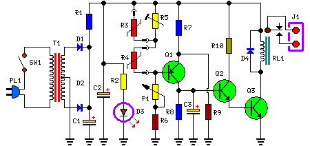
This circuit is designed to regulate a heating system or central heating, maintaining a consistent indoor temperature despite significant variations in the ambient temperature outside. Two sensors are required: one positioned outdoors, for sensing the external temperature, and the other located on the water pipe returning from the heating circuit, just before it enters the boiler.
The Relay contact wiring must be connected to the boiler's start-stop control input. This circuit, although simple, has proven to be extremely reliable; in fact, it was installed over 20 years ago at my parents' home. Despite its age, it continues to operate effectively and without any malfunctions.
Circuit diagram:
Parts
- P1 = 1K Linear Potentiometer
- R1 = 10R-1/4W Resistor
- R2 = 1K-1/4W Resistor
- R3 = 3K3 @ 20°C n.t.c. Thermistor (see Notes)
- R4 = 2K2 @ 20°C n.t.c. Thermistor (see Notes)
- R5 = 10K-1/2W Trimmer Cermet
- R6 = 3K3-1/4W Resistor
- R7 = 4K7-1/4W Resistors
- R8 = 470K-1/4W Resistor
- R9 = 4K7-1/4W Resistors
- R10 = 10K-1/4W Resistor
- C1 = 470µF-25V Electrolytic Capacitors
- C2 = 470µF-25V Electrolytic Capacitors
- C3 = 1µF-63V Electrolytic Capacitor
- D1 = 1N4002 - 100V 1A Diodes
- D2 = 1N4002 - 100V 1A Diodes
- D4 = 1N4002 - 100V 1A Diodes
- D3 = LED Red 3 or 5mm.
- Q1 = BC557 - 45V 100mA PNP Transistor
- Q2 = BC547 - 45V 100mA NPN Transistor
- Q3 = BC337 - 45V 800mA NPN Transistor
- J1 = Two ways output socket
- T1 = 220V Primary, 12 + 12V Secondary 3VA Mains transformer
- PL1 = Male Mains plug &cable
- SW1 = SPST Mains Switch
- RL1 = Relay with SPDT 2A @ 220V switch Coil Voltage 12V. Coil resistance 200-300 Ohm
Circuit operation:
When the BC557 (Q1) base-to-ground voltage falls below half the supply voltage (determined by R7 and R9), a voltage appears across R8, and the driver transistors BC547 (Q2) and BC337 (Q3) switch the Relay on. Conversely, when the BC557 (Q1) base-to-ground voltage exceeds half the supply voltage – caused by a decrease in the value of the n.t.c. thermistors due to an increase in ambient temperature – no voltage is generated across R8, and the Relay is deactivated. C3 facilitates a clean switching action for the Relay. P1 serves as the primary temperature control element.
Notes:
- R3 represents the outdoor sensor, and R4 the indoor sensor.
- If a 3K3 Thermistor is unavailable for R3, a 4K7 value can be substituted. Compensation for this difference can be easily achieved using the trimmer R5.
- R5 allows for calibration of the heating system to suit outdoor temperatures ranging from approximately +10°C down to colder values. A higher R5 resistance results in a hotter heating system, while a lower resistance setting creates a cooler output.
- The existing boiler thermostat should be left active and not bypassed, as this is crucial for safety.
- This circuit can be simplified by removing the differential feature, converting it into a basic precision thermostat, omitting R3.
Integrated Circuits:
The BC557 (Q1), BC547 (Q2), and BC337 (Q3) are NPN bipolar junction transistors. These transistors function as switching devices, amplifying small base currents into larger collector currents to control the Relay coil. The selection of these transistors offers suitable current handling capability (100mA) and voltage rating (45V) for the circuit's operation.
