- 700Hz Pulse Generator & Signal Tracer Circuit
- Build Your Own 66 Melody Generator Circuit Diagram
- Build Your Own 9V Surf Noise Simulator
- Build Your Own Music: UM66 Circuit Diagram (8 Ohm)
- Build Your Powerful 5-Tone Siren Circuit Diagram
- Cuckoo Song Generator: 667Hz & 545Hz
- DIY Bell Tone Generator Circuit Schematic
- Cricket Chirp Generator Circuit: Build Your Realistic Sound
- Build a 4-Tone Siren Circuit with One IC
- Build Your Own Electronic Canary: Circuit Diagram & Chirp Secrets
- Build Your 8 Sound Effects Generator with HT2884
- UM3561 Sound Effects Generator Circuit Diagram - Build Your Own!
- Low Distortion Audio Sine Wave Oscillator Circuit Diagram
- Cuckoo Sound Generator: Build Your Own Realistic Bird Song
- Dual Tone Siren Circuit Diagram – Build Your Own!
Build a 4-Tone Siren Circuit with One IC
Description
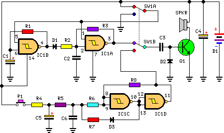
This circuit is designed for recreational use, suitable for incorporation into bicycles, battery-powered automobiles and motorcycles, alongside various models and assorted toys. When SW1 is positioned as depicted in the accompanying schematic, a conventional dual-tone effect, reminiscent of Police or Fire-brigade vehicle sounds, is produced due to the oscillation of gates within IC1A and IC1B. Conversely, with SW1 set to the alternative configuration, a reproduced old-style siren sound, characterized by an increasing frequency followed by a gradual decrease, is generated through actuation of P1, initiating oscillation in IC1C and IC1D.
The loudspeaker, driven by Q1, should be of an appropriate size and properly enclosed to achieve a more realistic and amplified output. The pitch and duration of the sound oscillations can be adjusted by modifying the values of C1, C2, C5, C6, and/or associated resistors. No power switch is necessary; maintain SW1 in the low position to minimize circuit power consumption.
Circuit diagram:
Parts:
- R1 = 470K - 1/4W Resistors
- R2 = 680K - 1/4W Resistor
- R3 = 470K - 1/4W Resistors
- R4 = 82K - 1/4W Resistor
- R5 = 330K - 1/4W Resistor
- R6 = 10K - 1/4W Resistor
- R7 = 33K - 1/4W Resistor
- R8 = 3.3M - 1/4W Resistor
- C1 = 10µF - 25V Electrolytic Capacitors
- C2 = 10nF - 63V Polyester Capacitors
- C3 = 100nF - 63V Polyester Capacitor
- C4 = 100µF - 25V Electrolytic Capacitor
- C5 = 10µF - 25V Electrolytic Capacitors
- C6 = 10nF - 63V Polyester Capacitors
- D1 = 1N4148 - 75V 150mA Diodes
- D2 = 1N4148 - 75V 150mA Diodes
- D3 = 1N4148 - 75V 150mA Diodes
- Q1 = BC337 - 45V 800mA NPN Transistor
- P1 = SPST Pushbutton
- B1 = 6V Battery (4 AA 1.5V Cells in series)
- IC1 = 4093 - Quad 2 input Schmitt NAND Gate IC
- SW1 = DPDT Switch
- SPKR= 8 Ohm Loudspeaker
IC1 - 4093 Quad 2 input Schmitt NAND Gate IC
The 4093 is a quad Schmitt gate IC. It comprises four independent Schmitt trigger gates, each with two inputs and one output. This specific IC is widely used in digital circuits for signal conditioning and noise filtering. The Schmitt trigger characteristic ensures that the output switches reliably even with small variations in the input signal. The IC’s stability makes it ideal for creating stable switching circuits, particularly when dealing with noisy environments. It is a valuable component for various electronic projects, offering robust signal handling and reliable switching performance. It provides a stable trigger output suitable for building timing circuits or level-shifting logic.
