- 700Hz Pulse Generator & Signal Tracer Circuit
- Build Your Own 66 Melody Generator Circuit Diagram
- Build Your Own 9V Surf Noise Simulator
- Build Your Own Music: UM66 Circuit Diagram (8 Ohm)
- Build Your Powerful 5-Tone Siren Circuit Diagram
- Cuckoo Song Generator: 667Hz & 545Hz
- DIY Bell Tone Generator Circuit Schematic
- Cricket Chirp Generator Circuit: Build Your Realistic Sound
- Build a 4-Tone Siren Circuit with One IC
- Build Your Own Electronic Canary: Circuit Diagram & Chirp Secrets
- Build Your 8 Sound Effects Generator with HT2884
- UM3561 Sound Effects Generator Circuit Diagram - Build Your Own!
- Low Distortion Audio Sine Wave Oscillator Circuit Diagram
- Cuckoo Sound Generator: Build Your Own Realistic Bird Song
- Dual Tone Siren Circuit Diagram – Build Your Own!
Build Your Own 66 Melody Generator Circuit Diagram
Description
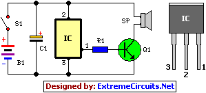
This straightforward melody creation circuit utilizes a particular integrated circuit. The UM66 series represents CMOS ICs, specifically created for implementation within calling bells, telephones, and recreational toys. These devices incorporate a pre-programmed ROM, enabling them to playback musical sequences. The system’s operation benefits from extremely low power consumption, thanks to advancements in CMOS technology. The audio output is available on pin 3 of the UM66, and is then boosted using transistor Q1 to drive the speaker effectively. Resistor R1 safeguards the base current of Q1, ensuring its operation remains within secure parameters. Capacitor C1 is included for minimizing electrical noise.
UM66 IC Details
The UM66 series of integrated circuits are CMOS devices primarily employed in applications such as calling bells, telephones, and children’s toys. These ICs feature a built-in ROM that stores musical sequences, enabling the devices to play these melodies automatically. Their low power consumption makes them ideal for battery-powered applications. The device’s operation is based on the CMOS technology, allowing low power consumption. The audio output is accessible via pin 3 and is amplified using the transistor Q1 to drive the speaker.
Circuit diagram:
Parts:
- R1 = 4.7K
- IC = UM66T
- Q1 = 2N2222
- C1 = 10uF-16v
- S1 = On/Off Switch
- B1 = 1.5 - 4.5 Battery
- SP = 2R Speaker
Notes:
- The power supply should be maintained within the range of 1.5V and 4.5V. Exceeding 4.5V is strictly prohibited.
- An external NPN transistor can be employed to drive the speaker.
- The melody will initiate playing from the initial note upon resetting the power supply.
- Assemble the circuit onto a robust, high-quality common printed circuit board.
