- CMOS Toggle Flip Flop: Laser Pointer Circuit Diagram
- CMOS Flip Flop Toggle Relay Circuit Diagram 4013
- MOSFET Relay Circuit: Build Your 6V Toggle System
- Build Your 12V Single Transistor Relay Circuit
- Relay Toggle Circuit: 556 Timer Delay Design
- 555 Timer Relay Toggle Circuit Diagram 100uF Capacitor
- Build a Robust MOSFET Toggle Switch Circuit – 12V, IRFZ44
- Build Your 8-Source Electronic Selector Circuit Diagram
- Build Your Own Toggle Relay Circuit – 5 to 15V Power
- Dual Relay Driver: Boost Sensitivity with BC547 Circuit
- 230V AC Toggle Switch Circuit: Build Your Own!
Build Your Own Toggle Relay Circuit – 5 to 15V Power
Description
This uncomplicated circuit will activate and deactivate a relay with a button press. Any type of momentary push-to-make switch can be employed. Pressing the button once – will energize the relay. And pressing it a second time – will de-energize the relay.
Schematic Diagram
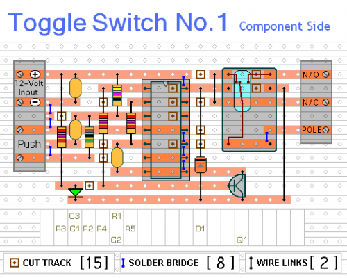
A single-pole relay has been depicted in the diagram. However, a multi-pole relay can be utilized if it best fits your specific requirements. Only one half of the Cmos 4013 is integrated. Consequently, it’s possible to build two independent toggle switches using just one IC. The circuit functions effectively across a voltage range of 5 to 15-volts. Simply choose a relay with a coil voltage that aligns with your power supply.
The LED provides a visual cue, indicating whether the relay is active or inactive. This element isn’t essential for the circuit’s operation. If desired, R3 and the LED can be omitted.
IMPORTANT
It is imperative not to utilize the internal relay to switch mains voltage. The board’s design lacks sufficient isolation between the relay contacts and the low-voltage components. If you intend to switch mains voltage, install a relay with an appropriate rating in a secure location – Away From The Board.
Veroboard Layout
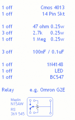
Part list
The Cmos 4013 is a versatile integrated circuit (IC) commonly employed as a versatile logic gate. This particular IC operates as a versatile, quadruple gate, offering four independent switching capabilities within a single package. The 4013 is known for its small size and ease of integration into digital circuits. It’s often used for creating digital circuits and logic gates. Its four independent gates enable the construction of more complex digital circuits and control logic. The IC has four independent inputs and four outputs, allowing for flexible digital circuit design.


