- CMOS Toggle Flip Flop: Laser Pointer Circuit Diagram
- CMOS Flip Flop Toggle Relay Circuit Diagram 4013
- MOSFET Relay Circuit: Build Your 6V Toggle System
- Build Your 12V Single Transistor Relay Circuit
- Relay Toggle Circuit: 556 Timer Delay Design
- 555 Timer Relay Toggle Circuit Diagram 100uF Capacitor
- Build a Robust MOSFET Toggle Switch Circuit – 12V, IRFZ44
- Build Your 8-Source Electronic Selector Circuit Diagram
- Build Your Own Toggle Relay Circuit – 5 to 15V Power
- Dual Relay Driver: Boost Sensitivity with BC547 Circuit
- 230V AC Toggle Switch Circuit: Build Your Own!
Relay Toggle Circuit: 556 Timer Delay Design
Description
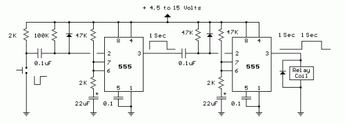
The schematic below demonstrates creating a solitary positive spike that is shifted in time relative to the initiating signal’s arrival. This design mirrors the previous one but utilizes two operational phases, enabling both the pulse’s duration and the delay to be adjusted. Upon pressing the button, the output of the initial stage will ascend and hold itself near the supply voltage until the specified delay period—approximately 1 second—has passed. The second 555 timer instance will not react to the rising voltage because it necessitates a negative, descending voltage at pin 2. Consequently, the second stage’s output remains inactive, and the relay remains unpowered. At the conclusion of the delay duration, the initial stage’s output reverts to a low state, and the falling voltage activates the second stage’s output cycle, also lasting around 1 second as depicted. This very circuit could be constructed using the dual 555 timer, often referred to as the 556, though the specific pin assignments will differ.
