- CMOS Toggle Flip Flop: Laser Pointer Circuit Diagram
- CMOS Flip Flop Toggle Relay Circuit Diagram 4013
- MOSFET Relay Circuit: Build Your 6V Toggle System
- Build Your 12V Single Transistor Relay Circuit
- Relay Toggle Circuit: 556 Timer Delay Design
- 555 Timer Relay Toggle Circuit Diagram 100uF Capacitor
- Build a Robust MOSFET Toggle Switch Circuit – 12V, IRFZ44
- Build Your 8-Source Electronic Selector Circuit Diagram
- Build Your Own Toggle Relay Circuit – 5 to 15V Power
- Dual Relay Driver: Boost Sensitivity with BC547 Circuit
- 230V AC Toggle Switch Circuit: Build Your Own!
555 Timer Relay Toggle Circuit Diagram 100uF Capacitor
Description
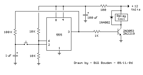
The following 555 timer circuit initiates a relay closure upon button activation. Pins 2 and 6, designated as the threshold and trigger inputs, are maintained at one-half of the supply voltage through two 10K resistors. Upon the output transitioning to a high state, the capacitor charges via the 100K resistor, and conversely, it discharges when the output becomes low. Button press applies the capacitor's voltage to pins 2 and 6, resulting in the output reversing its state. Release of the button allows the capacitor to charge or discharge, ultimately adjusting the output level (pin 3). Component values are adaptable, though maintaining equal resistor values at pins 2 and 6 and a resistor value at the capacitor ten times greater or higher is recommended for optimal performance.
Key benefits of this design encompass a substantial hysteresis range at the input, preventing spurious activations, and a minimal component count for assembly. However, a potential drawback exists: the relay could remain engaged immediately after power application. This can be mitigated by connecting the reset line (pin 4) to a separate resistor/capacitor combination, featuring a capacitor grounded and a resistor connected to the +V terminal. This arrangement ensures pin 4 is held near ground temporarily, effectively resetting the output upon power-up.
The 100 ohm resistor and 100uF capacitor are implemented to attenuate electrical disturbances on the power supply line, particularly pertinent when the circuit is deployed in automotive settings. These components are optional and may not be required for proper functionality. The circuit can operate effectively without them.
