- CMOS Toggle Flip Flop: Laser Pointer Circuit Diagram
- CMOS Flip Flop Toggle Relay Circuit Diagram 4013
- MOSFET Relay Circuit: Build Your 6V Toggle System
- Build Your 12V Single Transistor Relay Circuit
- Relay Toggle Circuit: 556 Timer Delay Design
- 555 Timer Relay Toggle Circuit Diagram 100uF Capacitor
- Build a Robust MOSFET Toggle Switch Circuit – 12V, IRFZ44
- Build Your 8-Source Electronic Selector Circuit Diagram
- Build Your Own Toggle Relay Circuit – 5 to 15V Power
- Dual Relay Driver: Boost Sensitivity with BC547 Circuit
- 230V AC Toggle Switch Circuit: Build Your Own!
MOSFET Relay Circuit: Build Your 6V Toggle System
Description
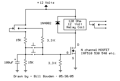
This circuit mirrors the one above, yet employs a N channel MOSFET, such as IRF530, 540, 640, or similar alternatives, instead of the NPN transistor. Smaller MOSFETs may be employed, however, specific part numbers are currently unknown. The circuit was validated using IRF640, IRFZ44, IRFZ34, and REP50N06 components.
The design retains its three key benefits: minimal component count, consistent default relay deactivation, and the elimination of switch debouncing requirements.
During deactivated operation, the 100µF capacitor accumulates voltage up to 6 volts. Activating the button then introduces 6 volts to the MOSFET's gate, triggering its conduction. The capacitor's voltage—and consequently, the gate voltage—decreases from 6 to 3 volts within approximately 200ms. This duration should sufficiently allow the relay contacts to move. For particularly sluggish relays, a larger capacitance might be necessary to compensate.
When the relay is energized, the contacts provide 12 volts across the 3.3K resistor, resulting in a 6-volt gate voltage. This sustains indefinite relay activation. The capacitor subsequently discharges entirely, as the +12 volt relay contact is no longer connected to the 15K resistor.
Upon re-pressing the button, the capacitor applies zero volts to the gate, disabling the MOSFET and, therefore, the relay. Issues arising from prolonged button holding to repeatedly re-engage the relay are avoided, as the gate voltage remains approximately 1.8 volts—a level insufficient for the MOSFET to conduct effectively. However, a wait period of roughly 1 second or longer is needed to permit the capacitor to fully recharge or discharge.
