- CMOS Toggle Flip Flop: Laser Pointer Circuit Diagram
- CMOS Flip Flop Toggle Relay Circuit Diagram 4013
- MOSFET Relay Circuit: Build Your 6V Toggle System
- Build Your 12V Single Transistor Relay Circuit
- Relay Toggle Circuit: 556 Timer Delay Design
- 555 Timer Relay Toggle Circuit Diagram 100uF Capacitor
- Build a Robust MOSFET Toggle Switch Circuit – 12V, IRFZ44
- Build Your 8-Source Electronic Selector Circuit Diagram
- Build Your Own Toggle Relay Circuit – 5 to 15V Power
- Dual Relay Driver: Boost Sensitivity with BC547 Circuit
- 230V AC Toggle Switch Circuit: Build Your Own!
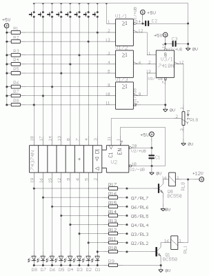
Build Your 8-Source Electronic Selector Circuit Diagram
Description
The Elect. Sel. 8 constitutes a straightforward circuit, offering a selection of eight diverse sources and eight individual switches. Each switch correlates with a relay, such as the activation of RL1 by S1, and so forth. The circuit’s applications are numerous, including selecting audio amplifier entries, command selection within digital circuits, and independent LED illumination where applicable.
More about components
Integrated circuits, specifically the 74LS374 and 74LS27, represent complex semiconductor devices that consolidate multiple electronic circuits onto a single chip. The 74LS374 is a versatile quadruple gate D-type flip-flop, allowing for the storage and manipulation of binary data. It’s frequently utilized in shift register designs and sequential logic circuits. The 74LS27 is a dual D-type flip-flop, providing two independent flip-flop circuits capable of storing and resetting binary data. These ICs are essential components in digital systems requiring memory and timing functions.
Circuit diagram
Part list
- R1-8=10Kohms
- R9=470 ohms
- R10-17= 4.7Kohms
- TR1=4.7Kohms Trimmer
- IC1=74LS374
- IC2=74LS27
- IC3=74LS10
- T1-8=BC550
- D1-8=Led 3mm
- C1-3=47nF 63V MKT
- RL1-8= 6-12V DC Relay
- S1-8=Push button SW
A warning regarding security is hereby presented. This circuit diagram and associated parts list have been compiled by John Smith. The information provided herein is sourced from Circuit Diagrams Online. Please exercise caution when working with electrical circuits.
