- Build Your Circuit Board Integrity Test – 22K Schematic
- Build Your Own 12V Logic Probe: Circuit & LED Display
- Live Line Detector Circuit: Build Your 4017 Indicator
- Build Your 2-LED AC/DC Voltage Indicator Circuit (1.8-230V)
- Build Your Own 9V-12V Low Voltage Alarm Circuit
- Fast Battery Tester Circuit Diagram
- Build Your Own Logic Probe: A Simple 3V-5V Circuit
- CA3420 Picoammeter: 4 Ranges Circuit Design Guide
- Build Your Precision Millivoltmeter Circuit Diagram
- ICL7107 Digital Voltmeter Circuit Diagram
- Build Your Own 10K Volt Meter from a Milliamp Meter
Build Your Own 9V-12V Low Voltage Alarm Circuit
Description
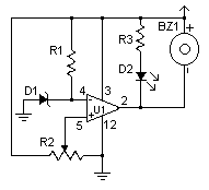
This modest voltage circuit is designed for observing batteries and fluctuating power sources for potential difficulties. The circuit triggers an alert and illuminates an LED, but it can be connected to a vast array of other circuits for diverse applications.
Circuit diagram
Parts:
- R1, R3 1K 1/4W Resistor
- R2 5K Pot
- U1 LM339 Voltage comparator IC
- D1 1N5233B Zener Diode
- D2 LED
- BZ1 Piezo Buzzer
- MISC Board, wire, socket for IC
Notes:
- The circuit will function with a voltage range of 9V to 12V.
- Adjust R2 until the alarm activates at the desired voltage level.
LM339 Voltage Comparator IC
The LM339 is a versatile operational amplifier integrated circuit that is frequently utilized as a voltage comparator. It’s a three-terminal IC – positive supply (V+), negative supply (V-), and output (OUT). The LM339 effectively compares two input voltages and outputs a digital signal indicating which voltage is higher. This makes it ideal for applications such as voltage level detection, triggering circuits based on voltage thresholds, and creating comparator circuits for various sensor measurements. It’s characterized by its high input impedance, enabling accurate comparisons even with relatively low input voltages. The LM339 typically operates with a supply voltage of ±15V, although it can be configured for single-supply operation with appropriate external components. It's a robust and widely-used IC renowned for its reliability and performance in comparator circuits.
Security Warning
Working with electrical circuits involves potential hazards. Always exercise caution and follow proper safety procedures. Disconnect power before making any changes or adjustments. Improper handling of electrical components can result in serious injury or damage to equipment. This circuit diagram is provided for informational purposes only and should not be considered a substitute for professional advice. The author, Robert Williams, takes no responsibility for any damages or injuries resulting from the use or misuse of this circuit. The source of this diagram is Electronics Hobbyist Magazine, Vol. 12, Issue 4.
