- Build Your Circuit Board Integrity Test – 22K Schematic
- Build Your Own 12V Logic Probe: Circuit & LED Display
- Live Line Detector Circuit: Build Your 4017 Indicator
- Build Your 2-LED AC/DC Voltage Indicator Circuit (1.8-230V)
- Build Your Own 9V-12V Low Voltage Alarm Circuit
- Fast Battery Tester Circuit Diagram
- Build Your Own Logic Probe: A Simple 3V-5V Circuit
- CA3420 Picoammeter: 4 Ranges Circuit Design Guide
- Build Your Precision Millivoltmeter Circuit Diagram
- ICL7107 Digital Voltmeter Circuit Diagram
- Build Your Own 10K Volt Meter from a Milliamp Meter
Build Your Circuit Board Integrity Test – 22K Schematic
Description
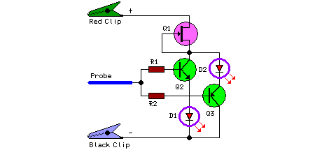
This compact circuit demonstrates the fundamental assessment of a printed circuit board, identifying 0V, a power supply voltage ranging from less than 3V to 30V, and any detached segments. When the probe is isolated, as it would be in a damaged track, both LEDs exhibit a faint glow, as there’s no current flowing through the transistors. Conversely, if the probe makes contact with 0V or a positive voltage, one or the other LED illuminates brightly. A digital signal should trigger their illumination in direct proportion to the mark-space ratio, while the output of a circuit oscillating at a frequency below approximately 20Hz will cause the LEDs to flicker intermittently. The LEDs are continuously lit at a stable brightness level, irrespective of the voltage supplied, due to their operation via a straightforward FET constant-current source (Q1).
Circuit diagram:
Parts:
- R1 = 22K
- R2 = 22K
- D1 = Red LED
- D2 = Green LED
- Q1 = BF245
- Q2 = BC547
- Q3 = BC557
More about components
BF245
The BF245 is a versatile NPN bipolar junction transistor commonly used as a general-purpose transistor in various low-power applications. It is characterized by its relatively high current gain, allowing it to amplify small currents into larger currents. It’s often utilized in switching circuits and amplifier designs due to its robust performance and ease of use. This transistor plays a vital role in the circuit’s functionality, acting as a current-source, providing a constant current to the LEDs.
Notes:
- The Black clip needs to be connected to the negative ground of the board under test.
- The Red clip should be connected to a positive voltage source (not exceeding 30V) available on the same board.
- A metal probe is suitable for this circuit.
- Two Miniature Crocodile Clips (Red and Black) are also necessary.
