similar circuits
- Build Your Circuit Board Integrity Test – 22K Schematic
- Build Your Own 12V Logic Probe: Circuit & LED Display
- Live Line Detector Circuit: Build Your 4017 Indicator
- Build Your 2-LED AC/DC Voltage Indicator Circuit (1.8-230V)
- Build Your Own 9V-12V Low Voltage Alarm Circuit
- Fast Battery Tester Circuit Diagram
- Build Your Own Logic Probe: A Simple 3V-5V Circuit
- CA3420 Picoammeter: 4 Ranges Circuit Design Guide
- Build Your Precision Millivoltmeter Circuit Diagram
- ICL7107 Digital Voltmeter Circuit Diagram
- Build Your Own 10K Volt Meter from a Milliamp Meter
home :: tools and measuring :: current and voltage :: build your precision millivoltmeter circuit diagram
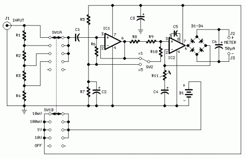
Build Your Precision Millivoltmeter Circuit Diagram
This circuit measures from 10mV to 50V RMS across eight different settings.
Simply connect it to your Avo-meter, configured for a 50uA current range.
Circuit Diagram
Components:
- R1 909K Ohm, a 1/2Watt, 1% Metal Oxide Resistor
- R2 90.09K Ohm, a 1/2Watt, 1% Metal Oxide Resistor
- R3 9.009K Ohm, a 1/2Watt, 1% Metal Oxide Resistor
- R4 1.001K Ohm, a 1/2Watt, 1% Metal Oxide Resistor
- R5 100K Ohm, a 1/4Watt Resistor
- R6 2.00M Ohm, a 1/4Watt Resistor
- R7 82.0K Ohm, a 1/4Watt Resistor
- R8 12.0K Ohm, a 1/4Watt Resistor
- R9 1.000K Ohm, a 1/4Watt Resistor
- R10 3.300K Ohm, a 1/4Watt Resistor
- R11 200R Ohm, a 1/2Watt Trimmer Cermet
- C1 330nF, 63V Polyester Capacitor
- C2, C3 100uF, 25V Electrolytic Capacitor
- C4 220uF, 25V Electrolytic Capacitor
- C5 33pF, 63V Polystyrene Capacitor
- C6 2.20uF, 63V Electrolytic Capacitor
- D1-D4 1N4148, 75V, 150mA Diodes
- IC1 CA3140 Operational Amplifier (Op-amp)
- IC2 CA3130 Operational Amplifier (Op-amp)
- SW1 2-pole, 5-way rotary switch
- SW2 SPDT switch
- J1 RCA audio input socket
- J2, J3 4mm. output sockets
- B1 9V PP3 Battery
- Clip for PP3 Battery
Notes:
- Connect J2 and J3 to your Avo-meter, configured for a 50uA current range
- Switching SW2 multiplies the four input ranges by a factor of 5
- The total available range is: 10mV, 50mV, 100mV, 500mV, 1V, 5V, 10V, 50V
- To calibrate R11, set it to read 1V within the 1V range, using a sine wave input of 1V at 1KHz
- Verify the reading against another known precision millivoltmeter or by observing the waveform on an oscilloscope – the oscilloscope reading should display a sine wave with a peak-to-peak amplitude of 2.828V
- The frequency response is flat across the 20Hz to 20KHz range
- If you encounter difficulty in locating the exact resistor values for R1, R2, R3, and R4, you can employ the following method:
- R1 = 10M Ohm + 1M Ohm in parallel
- R2 = 1M Ohm + 100K Ohm in parallel
- R3 = 100K Ohm + 10K Ohm in parallel
- R4 = 1.001K Ohm + 6.8K Ohm in parallel
- All resistors possess a 1% tolerance
Operational Amplifiers (ICs):
Operational Amplifiers
The CA3140 and CA3130 are both widely utilized integrated circuits, specifically designed as operational amplifiers. These devices are fundamental building blocks in many analog circuits, enabling amplification, filtering, and signal conditioning. They are characterized by their high gain, input impedance, and low offset voltage, making them suitable for a broad range of applications, from audio preamplifiers to instrumentation circuits. Their versatility and readily available pinouts contribute to their popularity in electronic design.
author: RED Free Circuit Designs
circuit from http://www.redcircuits.com/
circuit from http://www.redcircuits.com/
