similar circuits
- Build Your Circuit Board Integrity Test – 22K Schematic
- Build Your Own 12V Logic Probe: Circuit & LED Display
- Live Line Detector Circuit: Build Your 4017 Indicator
- Build Your 2-LED AC/DC Voltage Indicator Circuit (1.8-230V)
- Build Your Own 9V-12V Low Voltage Alarm Circuit
- Fast Battery Tester Circuit Diagram
- Build Your Own Logic Probe: A Simple 3V-5V Circuit
- CA3420 Picoammeter: 4 Ranges Circuit Design Guide
- Build Your Precision Millivoltmeter Circuit Diagram
- ICL7107 Digital Voltmeter Circuit Diagram
- Build Your Own 10K Volt Meter from a Milliamp Meter
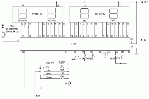
ICL7107 Digital Voltmeter Circuit Diagram
Circuit Diagram
A comprehensive collection of electrical circuit schematics is presented here, offering a diverse range of designs for educational and practical applications. These diagrams cover various electronic systems, providing a valuable resource for students, hobbyists, and professionals alike.The ICL7107 is a 3 1/2 digit LED Analog-to-Digital Converter. It incorporates an internal voltage reference, insulated analog switches, sequential control circuitry, and display drivers. The auto-zero adjustment feature guarantees a zero reading when an input of 0 volts is applied.
ICL7107 - Detailed Description
The ICL7107 is a versatile integrated circuit designed for converting analog signals into digital representations. This IC is particularly well-suited for applications requiring a 3 1/2 digit resolution, making it ideal for measuring voltage and current levels accurately. Its internal components, including the voltage reference and insulated analog switches, contribute to its stability and isolation characteristics. The sequential control logic enables a step-by-step conversion process, while the display drivers facilitate the output of the digital data. The auto-zero adjust function ensures the accuracy of the readings by compensating for any offsets or drift in the system. This feature is crucial for obtaining precise measurements, especially in environments with varying temperature or voltage fluctuations. The ICL7107 is a reliable and accurate solution for many measurement and control applications. [/P]
author: Zeus Electronics
circuit from http://www.geocities.com/
circuit from http://www.geocities.com/
