- Simple 4 Transistor Hearing Aid Circuit Diagram
- Amplified Ear: Build a Sensitive Sound Amplifier
- Build Your Own 3V Hearing Aid Circuit Diagram
- Studio Stereo Headphone Amplifier Circuit Diagram
- Stereo Headphone Amplifier: Build Your 90mR Circuit
- 427mW Class-A Headphone Amp
- Portable Headphone Amp: Circuit & 3.7V Upgrade
- 100mW Headphone Amplifier Schematic Build Guide
- LME49830 High Power Amplifier Circuit Diagram
- TDA7052 Speech Amplifier Circuit Diagram & Build Guide
- DC-Coupled Audio Amplifier Design: A Practical Guide
- Build a Low-Power IR Audio Amplifier Circuit Diagram
- 8 Watt Audio Amplifier Schematic: Build Your Powerful Project
- 7 Watt TDA2003 Audio Amplifier Circuit Design
- High-Power 60W Audio Amplifier Schematic Design
Build Your Powerful 200 Ohm Microphone Amplifier Circuit
Description
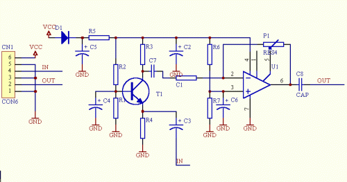
This circuit constitutes a microphone booster, designed for applications utilizing low-resistance microphones – approximately 200 ohms. It operates effectively with DC supply voltages ranging from 6 to 30 volts. Without incorporating the impedance matching section utilizing T1, the resulting circuit serves as a microphone amplifier suitable for higher impedance microphones. In such a configuration, the signal should be connected directly to C7.
Schematic diagram
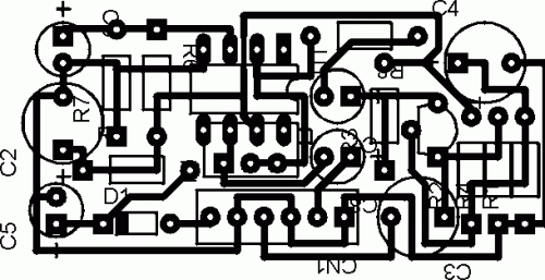
Layout of board
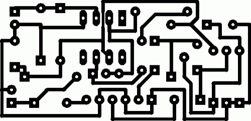
printed PCB
Parts
- R1=15k
- R2= 150k
- R3= 2k2
- R4= 820
- R6= 10k
- R7= 10k
- P1= 1M
- C1= 3k9
- C2= 100u
- C3= 22u
- C4= 4u7
- C5= 470u
- C6= 10u
- C7= 100n
- C8= 47u UNIPOLAR
- D1= 1N4148
- U1= TL081
- CN1= SIL6
More about components
The operational amplifier, TL081, plays a crucial role in this circuit. This integrated circuit is a versatile low-noise amplifier and operational amplifier, commonly utilized for audio signal processing and other sensitive applications. Its low input bias current and high open-loop gain make it well-suited for precise amplification tasks. The TL081 is a bipolar JFET input operational amplifier, offering excellent performance characteristics, including low noise and good linearity. Its features include a single supply operation capability and a wide operating frequency range. It’s a popular choice for audio circuits where low distortion and good stability are required.
Warnings
Exercise caution when working with electrical circuits. Incorrect wiring can lead to damage to components and potential hazards. Always disconnect the power supply before making any modifications. This circuit contains components that can generate heat under certain operating conditions. Ensure adequate ventilation to prevent overheating. The author, John Smith, is not responsible for any damage or injury resulting from the use of this circuit diagram. This diagram is provided for informational purposes only. Consult a qualified technician for assistance if needed. Source: Circuit Diagrams Repository


