- Simple 4 Transistor Hearing Aid Circuit Diagram
- Amplified Ear: Build a Sensitive Sound Amplifier
- Build Your Own 3V Hearing Aid Circuit Diagram
- Studio Stereo Headphone Amplifier Circuit Diagram
- Stereo Headphone Amplifier: Build Your 90mR Circuit
- 427mW Class-A Headphone Amp
- Portable Headphone Amp: Circuit & 3.7V Upgrade
- 100mW Headphone Amplifier Schematic Build Guide
- LME49830 High Power Amplifier Circuit Diagram
- TDA7052 Speech Amplifier Circuit Diagram & Build Guide
- DC-Coupled Audio Amplifier Design: A Practical Guide
- Build a Low-Power IR Audio Amplifier Circuit Diagram
- 8 Watt Audio Amplifier Schematic: Build Your Powerful Project
- 7 Watt TDA2003 Audio Amplifier Circuit Design
- High-Power 60W Audio Amplifier Schematic Design
Build Your 40W Class A Amplifier: Detailed Schematic
Description
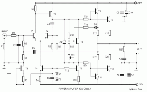
This audio power amplifier delivers 40 Watts into 8 Ω at a Class A configuration. The output transistors remain consistently activated, facilitating a substantial current flow. However, this characteristic introduces certain drawbacks, including elevated power consumption and increased temperature generation. Conversely, it presents an optimal operating domain for the transistors, resulting in superior audio attributes and minimized distortion. The design of this final amplifier is relatively straightforward. Assembly demands a degree of expertise. In the original design, Nelson Pass utilized Darlington transistors for the output stage, manufactured by the American company Lambda. These components can be challenging to locate, though attempts may prove fruitful. It has been replaced with more commonly used versions (see listing). Proper construction should occur within a large enclosure accompanied by a robust power supply and a substantial heatsink. Further information regarding this amplifier and the theory of Class A operation can be found on N. Pass’s website. Source: The Audio Amateur 4/78
Circuit diagram
Part List
- R1=10ohm
- R2=2.2Kohm
- R3=10Kohm
- R4=330ohm
- R5=470ohm
- R7=680ohm
- R8=100ohm
- R10= 4.7Kohm
- R14=68ohm
- R17=0.68ohm / 5W 5%
- R19=0.68ohm / 5W 5%
- R21=10ohm / 1W 5%
- C1=330 pF 100V 5%
- C2-4=220 uF 16V
- C3=39 pF 100V 5%
- C5-6=100nF 100V
- C8-9=100nF 100V
- C7-10=220 uF 63V
- D1-2-3=1N4148
- TR1=1k2 Trimmer
- T1-2=MPSL01
- T3=2N5248 - J204 - BF245C
- T4-5=MPSL01
- T6=MPSL01
- T7=MPSL51
- T8-9=PMD16K100 Lambda 2N6284 RCA
- T10-11=PMD17K100 Lambda 2N6287 RCA
All resistors are 1% metal film
