- Simple 4 Transistor Hearing Aid Circuit Diagram
- Amplified Ear: Build a Sensitive Sound Amplifier
- Build Your Own 3V Hearing Aid Circuit Diagram
- Studio Stereo Headphone Amplifier Circuit Diagram
- Stereo Headphone Amplifier: Build Your 90mR Circuit
- 427mW Class-A Headphone Amp
- Portable Headphone Amp: Circuit & 3.7V Upgrade
- 100mW Headphone Amplifier Schematic Build Guide
- LME49830 High Power Amplifier Circuit Diagram
- TDA7052 Speech Amplifier Circuit Diagram & Build Guide
- DC-Coupled Audio Amplifier Design: A Practical Guide
- Build a Low-Power IR Audio Amplifier Circuit Diagram
- 8 Watt Audio Amplifier Schematic: Build Your Powerful Project
- 7 Watt TDA2003 Audio Amplifier Circuit Design
- High-Power 60W Audio Amplifier Schematic Design
Build Your 8W TDA2030 Amplifier Circuit Diagram
Description
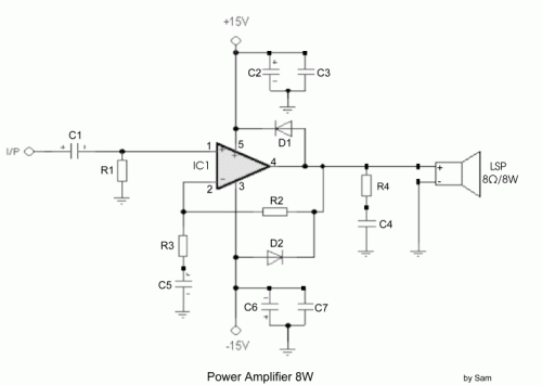
Despite the TDA2030’s capacity to produce 20 watts of output, a deliberate reduction to approximately 8 watts was implemented to adequately power 10 watt speakers. Input sensitivity is set at 200mV. Elevated input signals will naturally result in increased output, however, distortion should not be observed. The gain is controlled via the 47k and 1.5k resistors. The TDA2030 IC is a cost-effective option and a suitable alternative amplifier for low to medium audio power applications. Notably, speaker efficiency plays a crucial role in determining the perceived loudness of the music being played.
Integrated Circuit Details
The TDA2030 is a monolithic integrated circuit, a complex semiconductor device fabricated on a single silicon wafer. This particular IC is a highly popular audio amplifier, frequently utilized in small-scale amplifier designs. It's a dual operational amplifier, meaning it incorporates two independent amplifier stages within a single package. Its internal circuitry provides high gain, allowing it to effectively amplify weak audio signals. The TDA2030 is known for its relatively low distortion characteristics and is often selected for its robust performance and ease of use. It’s typically configured as a push-pull amplifier, offering improved linearity and power output compared to single-ended designs. The IC is commonly found in portable radio equipment, car audio systems, and other low-power audio applications. It requires careful power supply filtering to minimize noise and ensure stable operation. Its internal protection circuitry helps safeguard against overcurrent and overheating, further enhancing its reliability. The TDA2030 also features a built-in current limit function which is crucial for preventing damage to the amplifier and the connected speakers.
Circuit diagram
Part List
- R1-2=47ohmK 1/4W
- R3= 1.5Kohm 1/4W
- R4=1.2ohm /1W
- C1-5=1uF/25V
- C2-6=100uF/25V
- C3-7=100nF/63V
- C4=220nF/63V
- D1-2=1N4001
- IC1=TDA 2030
A security warning: Improper use of electronic circuits can result in electric shock, fire, or damage to equipment. Exercise caution and follow all safety guidelines when working with electrical components. Always disconnect the power supply before making any changes to the circuit. This circuit diagram is provided for informational purposes only and should be used at your own risk. The author assumes no responsibility for any damages or injuries that may result from the use of this diagram. Please consult a qualified electronics technician if you are unsure about any aspect of this circuit.
