- Simple 4 Transistor Hearing Aid Circuit Diagram
- Amplified Ear: Build a Sensitive Sound Amplifier
- Build Your Own 3V Hearing Aid Circuit Diagram
- Studio Stereo Headphone Amplifier Circuit Diagram
- Stereo Headphone Amplifier: Build Your 90mR Circuit
- 427mW Class-A Headphone Amp
- Portable Headphone Amp: Circuit & 3.7V Upgrade
- 100mW Headphone Amplifier Schematic Build Guide
- LME49830 High Power Amplifier Circuit Diagram
- TDA7052 Speech Amplifier Circuit Diagram & Build Guide
- DC-Coupled Audio Amplifier Design: A Practical Guide
- Build a Low-Power IR Audio Amplifier Circuit Diagram
- 8 Watt Audio Amplifier Schematic: Build Your Powerful Project
- 7 Watt TDA2003 Audio Amplifier Circuit Design
- High-Power 60W Audio Amplifier Schematic Design
12W NE5534 Audio Amplifier Circuit Diagram
Description
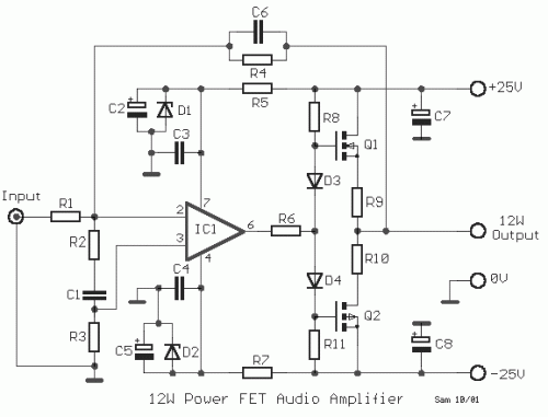
This modest audio amplifier delivers exceptional sound quality. It incorporates a high-performing integrated circuit, the NE5534, which offers control over light loads, rapid response times, minimal distortion, and two V-MOSFET transistors at its output. Replacement of component IC1 is possible with alternative equivalents, accompanied by an increase in the power supply voltage at the output stage, while meticulously maintaining the supply voltage levels to those specified for IC1, thereby maximizing the delivered output power. Operation in stereo mode is planned for implementation utilizing two separate units.
NE5534
The NE5534 is a widely-used operational amplifier renowned for its robustness and versatility. It’s characterized by its ability to manage low loads efficiently, respond quickly to changes in signal, and produce minimal harmonic distortion. Its two V-MOSFET output transistors provide substantial current drive capability. It’s a dependable choice for various audio applications where precise control and low distortion are critical.
Circuit diagram
Specifications
- Output Power - 12W in 8Ω (maximum)
- Input Sensitivity - 3.2V rms (maximum)
- Total Harmonic Distortion (THD) - 0.002% (1kHz)
- Frequency Response - DC - 100 kHz (-3dB)
Part List
- R1= 33Kohm
- R2= 6.8Kohm
- R3= 22Kohm
- R4= 100Kohm
- R5-7= 1Kohm
- R6= 330ohm
- R8-11= 10Kohm
- R9-10= 0.47ohm 2W
- C1= 1nF 63V
- C2-5= 47uF 40V
- C3-4= 100nF 63V
- C6= 4.7pF ceramic
- C7-8= 100uF 40V
- D1-2= 18V 0.5W zener
- D3-4= 1N4148
- IC1= NE5534
- Q1= 2SK135
- Q2= 2SJ50
