similar circuits
- Simple 4 Transistor Hearing Aid Circuit Diagram
- Amplified Ear: Build a Sensitive Sound Amplifier
- Build Your Own 3V Hearing Aid Circuit Diagram
- Studio Stereo Headphone Amplifier Circuit Diagram
- Stereo Headphone Amplifier: Build Your 90mR Circuit
- 427mW Class-A Headphone Amp
- Portable Headphone Amp: Circuit & 3.7V Upgrade
- 100mW Headphone Amplifier Schematic Build Guide
- LME49830 High Power Amplifier Circuit Diagram
- TDA7052 Speech Amplifier Circuit Diagram & Build Guide
- DC-Coupled Audio Amplifier Design: A Practical Guide
- Build a Low-Power IR Audio Amplifier Circuit Diagram
- 8 Watt Audio Amplifier Schematic: Build Your Powerful Project
- 7 Watt TDA2003 Audio Amplifier Circuit Design
- High-Power 60W Audio Amplifier Schematic Design
Bridged Power Amplifiers: Schematics & Parts Lists
Description
It constitutes a small assortment of amplifiers configured in a bridge arrangement. The output power delivered is modest, making it suitable for general applications. These circuits can be utilized with compact active loudspeakers and car stereos. A key requirement is that loudspeakers possessing a resistance value exceeding 4 ohms should be employed.
It consists of a small group of amplifiers connected in a bridge configuration. The output power produced is relatively low, rendering it appropriate for general-purpose use. These circuits can be utilized with small active loudspeakers and car stereos. A critical limitation is that loudspeakers having a resistance of more than 4 ohms must be implemented.
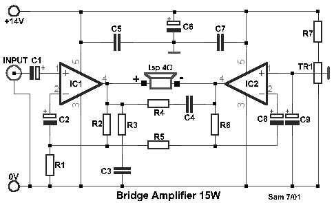
Circuit diagram: Bridged Amplifier 15W/4Ω
Parts list
- R1-5=2.7ohms
- R2=100ohms
- R3-4=2.2ohms
- R6=220ohms
- R7=1Mohms
- C1-9=10uF 16V
- C2-8=220uF 16V
- C3-4-5-7=100nF 63V
- C6=470uF 25V
- IC1-2=TDA2002
- TR1=100Kohms trimmer
- Lsp=4....8ohms/40W Loundspeaker
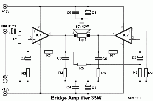
Circuit diagram: Bridged Amplifier 35W/8Ω
Parts list
- R1-3-5-7-9=22Kohms
- R2-8=680ohms
- R4-6=1ohm
- C1=4.7uF 16V
- C2-7=22uF 16V
- C3-6=220nF 100V
- C4-9=100nF 100V
- C5-8=200uF 25V
- IC1-2=TDA2030 --LM1875
- Lsp=8ohms/ 60W Loudspeaker
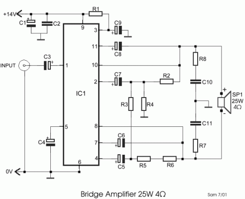
Circuit diagram: Bridge power amplifier 25W/4Ω
Parts list
- R1=120Kohms
- R2-5-6=1Kohms
- R3-4=12 ohms
- R7-8=1 ohm
- C1-5-7=220uF 25V
- C2-10-11=100nF 100V
- C3-4=2.2uF 25V
- C6-8=100uF 25V
- C9=10uF 25V
- IC1=LM2005M....TDA2005
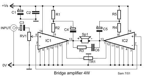
Circuit diagram: Bridge power amplifier [Po=1W Sp1=4Ω Vs=+6V] [Po=4W Sp1=8Ω Vs=+12V]
Parts list
- R1-2-4-5=270ohms
- R3=2.7ohms
- VR1=10Kohms Log. Pot.
- TR1=470Kohms Trimmer
- C1=100uF 25V
- C2=100nF 100V
- C3=10uF 25V
- C4-5=22uF 25V
- C6=47nF 100V
- IC1-2= LM388
circuit from http://users.otenet.gr/~athsam/bridge_amplifier.htm


