- Simple 4 Transistor Hearing Aid Circuit Diagram
- Amplified Ear: Build a Sensitive Sound Amplifier
- Build Your Own 3V Hearing Aid Circuit Diagram
- Studio Stereo Headphone Amplifier Circuit Diagram
- Stereo Headphone Amplifier: Build Your 90mR Circuit
- 427mW Class-A Headphone Amp
- Portable Headphone Amp: Circuit & 3.7V Upgrade
- 100mW Headphone Amplifier Schematic Build Guide
- LME49830 High Power Amplifier Circuit Diagram
- TDA7052 Speech Amplifier Circuit Diagram & Build Guide
- DC-Coupled Audio Amplifier Design: A Practical Guide
- Build a Low-Power IR Audio Amplifier Circuit Diagram
- 8 Watt Audio Amplifier Schematic: Build Your Powerful Project
- 7 Watt TDA2003 Audio Amplifier Circuit Design
- High-Power 60W Audio Amplifier Schematic Design
Build Your Own 6V6 Tube Amplifier Circuit
Description
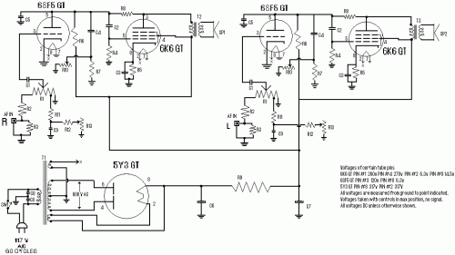
This circuit demonstrates remarkable performance despite its straightforward design. It was specifically crafted for use as an amplifier for the audio input of a computer’s digital sound card. Audio signals can originate from various two-channel line-level devices, including televisions, CD players, or VCRs. The design utilizes a tube-based approach, employing a total of five tubes with a maximum power consumption of approximately 45 Watts from the mains. The circuit incorporates three distinct tube types: 1 5Y3 GT vacuum rectifier, 2 6SF5 GT high-mu triodes, and 2 6K6 power beam amplifiers. These components are all full-size octal-type tubes, readily available today and typically priced between $3 and $5 each.
More about components
Integrated circuits play a crucial role in this circuit’s functionality. Specifically, ceramic disc capacitors are utilized. These capacitors are characterized by their robust construction and stability, offering superior performance compared to traditional electrolytic capacitors, particularly in applications involving temperature fluctuations and vibration. Their sealed construction provides protection against moisture and contaminants, further enhancing their reliability. Ceramic disc capacitors are frequently employed in audio circuits for their low equivalent series resistance (ESR) and low dissipation factor, minimizing signal distortion and ensuring accurate amplification. These characteristics are vital for maintaining the fidelity of the amplified audio signal.
Circuit Diagram
Parts:
- R1, R10, R13 2.2Meg Pot
- R2 470K 1/2W Resistor
- R3 1 Meg 1/2W Resistor
- R4 220K 1/2W Resistor
- R5 330 Ohm 2W Resistor
- R6 220K 1/2W Resistor
- R7 2.2Meg 1/2W Resistor
- R8 1Meg 1/2W Resistor
- R9 720 Ohm 20W Resistor
- R11 33K 1/2W Resistor
- R12 22K 1/2W Resistor
- C1, C9 0.005uF 400V Capacitor
- C2 0.05uF 600V Capacitor
- C3 20uF 25V Electrolytic Capacitor
- C4 0.01uF 400V Capacitor
- C5 200uuF 400V Ceramic Disc Capacitor
- C6, C7 15uF 450V Capacitor
- C8 15uF 400V Capacitor
- T1 117V Primary, 350VCT Secondary, 6.3V Secondary, 6.3V Secondary
- T2 7600 Ohm Primary, 4 or 8 Ohm Secondary
- SW1 SPST Switch
- SP1, SP2 12" or smaller, 4 or 8 ohm speakers
- MISC 5 tube sockets, 2 RCA jacks, PC board or chassis, wire, knobs, etc.
Notes:
- Contact Weslee Kinsler with inquiries, feedback, and suggestions.
- Substitution of the 6V6 GT tube for the 6K6 is possible to reduce power consumption.
- The C8 component serves for radio frequency interference suppression and can be omitted if desired.
- The 5Y3 GT tube should be mounted vertically and with adequate ventilation. The 6K6 and 6SF5 tubes can be mounted in any orientation.
- Controls should be equipped with an audio taper.
- The power supply section of this unit can be utilized for applications needing 290-320v DC, delivering approximately 3 amps.
circuit from http://www.aaroncake.net/
