- Simple 4 Transistor Hearing Aid Circuit Diagram
- Amplified Ear: Build a Sensitive Sound Amplifier
- Build Your Own 3V Hearing Aid Circuit Diagram
- Studio Stereo Headphone Amplifier Circuit Diagram
- Stereo Headphone Amplifier: Build Your 90mR Circuit
- 427mW Class-A Headphone Amp
- Portable Headphone Amp: Circuit & 3.7V Upgrade
- 100mW Headphone Amplifier Schematic Build Guide
- LME49830 High Power Amplifier Circuit Diagram
- TDA7052 Speech Amplifier Circuit Diagram & Build Guide
- DC-Coupled Audio Amplifier Design: A Practical Guide
- Build a Low-Power IR Audio Amplifier Circuit Diagram
- 8 Watt Audio Amplifier Schematic: Build Your Powerful Project
- 7 Watt TDA2003 Audio Amplifier Circuit Design
- High-Power 60W Audio Amplifier Schematic Design
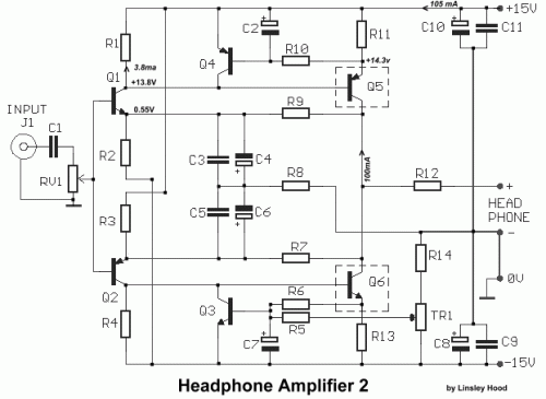
Class A Headphone Amplifier Circuit Diagram (1998)
Description
It is a valuable asset to possess a compact headphone amplifier, capable of powering a few sets of mobile phones. Thankfully, this amplifier has a simplified task, as neither the power output demands nor the load characteristics are particularly demanding, considering headphones usually present a load, impedance, often reaching 600 ohm, typically 50 ohm, and only require 1-2V RMS maximum, for standard operation. Because only minimal power is needed, a Class A stage proves to be a viable solution. For adequate Class A performance, the output transistors Q5, Q6, should handle approximately 100mA each. With a ±15V power supply, this would result in 1.5 Watts of heat dissipation, necessitating a small heat sink for each. RV1 is utilized to adjust the input audio signal, while Tr1 is configured to modify the output DC Offset voltage, setting it to 0V (±30mV). For a stereo application, two instances of this amplifier are required.
Circuit diagram
Part List
- R1-4= 1.2Kohm
- R2-3= 3.9Kohm
- R5=100Kohm
- R6-10= 10Kohm
- R7-9= 2.2Kohm
- R8= 150 ohm
- R11-13= 6R8 ohm
- R12= 4.7 ohm
- R14=68Kohm
- RV1= 10Kohm Log. pot.
- TR1= 10Kohm Trimmer
- C1= 4.7uF 63V MKT
- C2-7= 100uF 25V
- C3-5= 100nF 100V MKT
- C4-6= 100uF 16V
- C8-10= 470uF 25V
- C9-11= 100nF 100V ceramic
- Q1-3= BC184
- Q2-4= BC214
- Q5= BD136 or BD538
- Q6= BD135 or BD537
More about components
The integrated circuits incorporated within this design play a crucial role in amplifying the audio signal. Specifically, the BC184 (Q1-3) and BC214 (Q2-4) are general-purpose NPN transistors serving as the core amplification stages. These transistors are selected for their balanced performance characteristics, providing sufficient gain for the audio signal while maintaining low distortion. The BD136 or BD538 (Q5) and BD135 or BD537 (Q6) are used as output stages, providing high current drive capability to handle the load impedance of the headphones. These transistors are chosen for their robust performance and ability to deliver the required power without excessive heat dissipation. These ICs are vital components in this circuit design, ensuring efficient and reliable audio amplification.
circuit from http://users.otenet.gr/~athsam/headphone_2.htm
