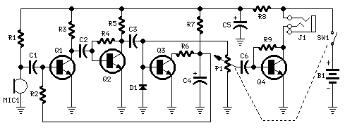
- Simple 4 Transistor Hearing Aid Circuit Diagram
- Amplified Ear: Build a Sensitive Sound Amplifier
- Build Your Own 3V Hearing Aid Circuit Diagram
- Studio Stereo Headphone Amplifier Circuit Diagram
- Stereo Headphone Amplifier: Build Your 90mR Circuit
- 427mW Class-A Headphone Amp
- Portable Headphone Amp: Circuit & 3.7V Upgrade
- 100mW Headphone Amplifier Schematic Build Guide
- LME49830 High Power Amplifier Circuit Diagram
- TDA7052 Speech Amplifier Circuit Diagram & Build Guide
- DC-Coupled Audio Amplifier Design: A Practical Guide
- Build a Low-Power IR Audio Amplifier Circuit Diagram
- 8 Watt Audio Amplifier Schematic: Build Your Powerful Project
- 7 Watt TDA2003 Audio Amplifier Circuit Design
- High-Power 60W Audio Amplifier Schematic Design
Constant-Volume Amplified Ear Circuit Design
Circuit Diagram
Components:
- P1 is a 22K Logarithmic Potentiometer (refer to Notes)
- R1, R9 are 10K 1/4W Resistors
- R2 is a 1M 1/4W Resistor
- R3 is a 4.7K 1/4W Resistor
- R4, R7 are 100K 1/4W Resistors
- R5 is a 3.9K 1/4W Resistor
- R6 is a 1.5K 1/4W Resistor
- R8 is a 100R 1/4W Resistor
- C1, C2 are 100nF 63V Polyester or Ceramic Capacitors
- C3, C6 are 1uF 63V Polyester or Ceramic Capacitors
- C4 is a 10uF 25V Electrolytic Capacitor
- C5 is a 470uF 25V Electrolytic Capacitor
- D1 is a 1N4148 75V 150mA Diode
- Q1, Q2, Q3 are BC547 45V 100mA NPN Transistors
- Q4 is a BC337 45V 800mA NPN Transistor
- MIC1 represents a Miniature electret microphone
- SW1 is a SPST Switch (Ganged with P1)
- J1 is a Stereo 3mm. Jack socket
- B1 is a 1.5V Battery (AA or AAA cell etc.)
Device Purpose:
This circuit, when connected with a 32 Ohm impedance mini-earphone, facilitates the detection of sounds originating from considerable distances. It’s particularly useful in settings such as theatres, cinemas, and lecture halls, ensuring that every spoken word is clearly audible. Additionally, it allows for listening to television sets at very low volume levels, preventing disturbance to relatives and neighbours. Even individuals with perfect hearing may discover unexpected sounds, such as the distant twittering of a bird, which will appear remarkably close.
Circuit Operation:
The central element of this circuit is a constant-volume control amplifier. All signals acquired by the microphone are amplified at a stable level of approximately 1 Volt peak to peak. This ensures that extremely low-amplitude audio signals are significantly amplified, while high-amplitude signals are limited. This functionality is achieved through Q3, which adjusts the bias of Q1 (thereby modifying its AC gain) utilizing R2. A notable characteristic of this circuit is its operation powered by a 1.5V battery. Typical current consumption is 7.5mA.
Notes:
- Due to the constant-volume control, certain users might consider P1 redundant. In most circumstances, it can be omitted, connecting C6 to C3. In such cases, a SPST slider or toggle switch should be employed as SW1.
- Pay attention to the stereo output Jack socket (J1) connections: only the two inner connections should be utilized, leaving the external one unconnected. This configuration wires the two earpieces in series, enabling mono operation and an optimal load impedance for Q4 (64 Ohms).
- Utilizing suitable miniature components, this circuit can be housed within a compact enclosure, provided by a clip, and hung on one’s clothing or slipped into a pocket.
circuit from http://www.redcircuits.com/
