- Simple 4 Transistor Hearing Aid Circuit Diagram
- Amplified Ear: Build a Sensitive Sound Amplifier
- Build Your Own 3V Hearing Aid Circuit Diagram
- Studio Stereo Headphone Amplifier Circuit Diagram
- Stereo Headphone Amplifier: Build Your 90mR Circuit
- 427mW Class-A Headphone Amp
- Portable Headphone Amp: Circuit & 3.7V Upgrade
- 100mW Headphone Amplifier Schematic Build Guide
- LME49830 High Power Amplifier Circuit Diagram
- TDA7052 Speech Amplifier Circuit Diagram & Build Guide
- DC-Coupled Audio Amplifier Design: A Practical Guide
- Build a Low-Power IR Audio Amplifier Circuit Diagram
- 8 Watt Audio Amplifier Schematic: Build Your Powerful Project
- 7 Watt TDA2003 Audio Amplifier Circuit Design
- High-Power 60W Audio Amplifier Schematic Design
50mW Low Power Op-Amp Audio Amplifier Circuit Diagram
Description
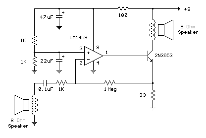
The following illustration demonstrates the utilization of a operational amplifier (op-amp) as a sound amplifier for a basic intercom system. A diminutive 8-ohm loudspeaker is employed as a microphone, coupled to the op-amp’s input via a 0.1 microfarad capacitor. The speaker is sensitive to low frequencies, and the small capacitance value is employed to diminish the lower tones, resulting in an improved overall frequency response. It is possible to modify the value of the capacitors to optimize the response for various speakers. The op-amp’s voltage gain is determined by the ratio of the feedback resistor to the series input resistor, approximately one thousand (1 Meg / 1K) in this instance. The non-inverting input (pin 3) to the op-amp is biased at 50% of the power supply voltage (4.5 volts) through a pair of 1K resistors connected across the supply. Because both inputs will be equal when the op-amp is operating within its linear range, the voltage at the inverting input (pin 2) and the emitter of the buffer transistor (2N3053) will also be 4.5 volts. A change in voltage at the emitter of the transistor will be around +/- 2 volts for a 2 millivolt change at the input (junction of 0.1 cap and 1K resistor) which produces a current change of about 2/33 = 60 mA through the 33-ohm emitter resistor and the speaker output. The maximum output speaker power is approximately I^2 * R or .06 ^2 * 8 = 28 milliwatts. The 100-ohm resistor and 47 microfarad capacitor are used to shield the op-amp from the power supply and mitigate the possibility of oscillation. Furthermore, a 22 microfarad capacitor is implemented at the non-inverting input to further stabilize operation. These components may not be necessary in such a low-power circuit, but it is advisable to decouple the power supply to prevent unwanted feedback. The circuit consumes approximately 1.2 watts from a 9-volt source and is not particularly efficient, yet remains relatively straightforward to construct. The circuit was tested employing a couple 4-inch speakers positioned several feet apart (to reduce feedback) and a small pocket transistor radio placed on top of the speaker/microphone as an audio source.
Operational Amplifier (Op-Amp)
An operational amplifier, or op-amp, is a high-gain, direct-coupled amplifier with differential inputs and a single-ended output. It is a crucial component in numerous electronic circuits, offering versatility in amplification, filtering, and signal processing. The 2N3053 transistor acts as a buffer, providing a high input impedance and reducing the load on the op-amp. The op-amp’s gain is primarily determined by the external resistor values in the feedback loop, enabling precise control over the amplified output signal. Its key characteristic is its ability to amplify small voltage differences between its inputs, making it ideal for precision amplification and signal conditioning.
Transistor (2N3053)
The 2N3053 is a general-purpose NPN silicon transistor, commonly used as a buffer amplifier. Its primary function in this circuit is to provide a high input impedance at the output, safeguarding the op-amp from loading effects. This is achieved through its base-emitter junction, which can drive a moderate current while maintaining a stable voltage. Its high current gain allows it to efficiently amplify small changes in voltage, further enhancing the overall performance of the intercom system. It also serves as a current source, providing a consistent current flow to the speaker.
