- Simple 4 Transistor Hearing Aid Circuit Diagram
- Amplified Ear: Build a Sensitive Sound Amplifier
- Build Your Own 3V Hearing Aid Circuit Diagram
- Studio Stereo Headphone Amplifier Circuit Diagram
- Stereo Headphone Amplifier: Build Your 90mR Circuit
- 427mW Class-A Headphone Amp
- Portable Headphone Amp: Circuit & 3.7V Upgrade
- 100mW Headphone Amplifier Schematic Build Guide
- LME49830 High Power Amplifier Circuit Diagram
- TDA7052 Speech Amplifier Circuit Diagram & Build Guide
- DC-Coupled Audio Amplifier Design: A Practical Guide
- Build a Low-Power IR Audio Amplifier Circuit Diagram
- 8 Watt Audio Amplifier Schematic: Build Your Powerful Project
- 7 Watt TDA2003 Audio Amplifier Circuit Design
- High-Power 60W Audio Amplifier Schematic Design
Improved 80mW Transistor Audio Amp with Positive Feedback
Description
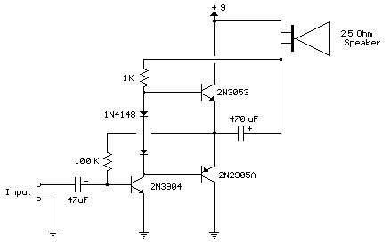
This circuit resembles the one above in its design, utilizing positive feedback to enhance the signal amplitude directed towards the speaker. This circuit was replicated from a miniature 5-transistor radio that employed a 25-ohm speaker. Within the circuit depicted above, the load resistor for the driver transistor is directly connected to the positive supply. A disadvantage of this configuration is that as the output shifts towards positive values, the voltage drop across the 470-ohm resistor diminishes, subsequently reducing the base current supplied to the top NPN transistor. Consequently, the output cannot achieve its maximum potential due to the absence of voltage across the 470-ohm resistor and a lack of base current to activate the NPN transistor.
This circuit partially addresses this issue, enabling a greater voltage swing and likely increasing the output power; however, the precise amount can only be determined through extensive testing. The output will still be limited to a couple of volts when utilizing small transistors, given that the peak current will not exceed 100mA when driving a 25-ohm load. Nonetheless, it represents an improvement over the initial circuit.
Within this design, the 1K load resistor is linked to the speaker, such that when the output moves negatively, the voltage across the 1K resistor decreases, aiding in the deactivation of the top NPN transistor. Conversely, when the output shifts positively, the charge stored on the 470uF capacitor assists in the activation of the top NPN transistor.
The original circuit found within the radio utilized a 300-ohm resistor where the two diodes are displayed, but this resistor was replaced with two diodes to improve amplifier operation at reduced voltages with minimized distortion. The transistors shown – 2n3053 and 2n2905 – were selected for use in the aforementioned circuit and could be substituted with smaller types. Nearly any small transistor is suitable for use, but it must be capable of delivering a current of 100mA or more under load. A 2N3904 or 2N3906 might be slightly undersized, yet they would function at low volume levels.
The two diodes generate a relatively stable bias voltage as the battery discharges and mitigate crossover distortion. It's crucial to ensure the idle current remains around 10 to 20 milliamps with no signal applied, and the output transistors should not overheat under load conditions.
This circuit is expected to function with a standard 8-ohm speaker; however, the output power might be somewhat diminished. To optimize operation, select a resistor where the 100K value is shown to set the output voltage to one-half of the supply voltage (4.5 volts). This resistor value can range from 50K to 700K, contingent on the gain of the transistor used where the 3904 is depicted.
