- Simple 4 Transistor Hearing Aid Circuit Diagram
- Amplified Ear: Build a Sensitive Sound Amplifier
- Build Your Own 3V Hearing Aid Circuit Diagram
- Studio Stereo Headphone Amplifier Circuit Diagram
- Stereo Headphone Amplifier: Build Your 90mR Circuit
- 427mW Class-A Headphone Amp
- Portable Headphone Amp: Circuit & 3.7V Upgrade
- 100mW Headphone Amplifier Schematic Build Guide
- LME49830 High Power Amplifier Circuit Diagram
- TDA7052 Speech Amplifier Circuit Diagram & Build Guide
- DC-Coupled Audio Amplifier Design: A Practical Guide
- Build a Low-Power IR Audio Amplifier Circuit Diagram
- 8 Watt Audio Amplifier Schematic: Build Your Powerful Project
- 7 Watt TDA2003 Audio Amplifier Circuit Design
- High-Power 60W Audio Amplifier Schematic Design
Build Your 325mW Bench Amplifier Circuit
Description:
A compact 325mW amplifier featuring a voltage amplification factor of 200 is provided. This device can be utilized as a laboratory amplifier, a signal tracer, or for boosting the output from portable radios, among other applications.
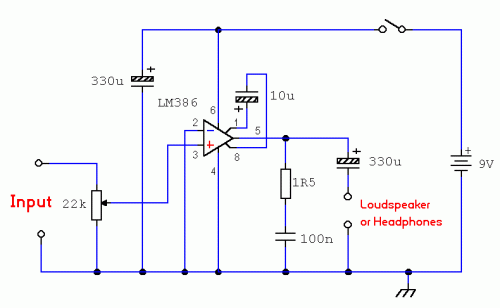
Circuit diagram
Notes:The circuit’s foundation rests upon the National Semiconductor LM386 amplifier. The diagram above illustrates a complete non-inverting amplifier, achieving a voltage gain of multiplied by two. A PDF datasheet from the National Semiconductor website is available for download. This integrated circuit is accessible in an 8-pin DIL package, with several versions existing; the LM386N-1 delivers 325mW output into an 8-ohm load, the Lm386N-3 offers 700mW output and the LM386N-4 provides 1000mW output. All versions function effectively within this circuit design.
The gain of the LM386 can be adjusted through the capacitor positioned across pins 1 and 8. When employing a 10uF capacitor as shown, the voltage gain is 200. Removing this capacitor results in a gain of 20 for the amplifier.
This integrated circuit operates from a supply of 4 to 12 Volts DC, with 12 Volts being the maximum recommended voltage. The internal input impedance of the amplifier is 50K ohms, which is bypassed by a 22K log potentiometer. This adjustment reduces the input impedance in the circuit to approximately 15K ohms. It is crucial to note that the input is DC coupled; therefore, caution must be taken to prevent amplifying any DC signal from preceding circuits, as this could potentially damage the loudspeaker. A coupling capacitor may be included in series with the 22K control to mitigate this risk.
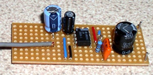
The finished circuit
circuit from http://www.zen22142.zen.co.uk/

