- Simple 4 Transistor Hearing Aid Circuit Diagram
- Amplified Ear: Build a Sensitive Sound Amplifier
- Build Your Own 3V Hearing Aid Circuit Diagram
- Studio Stereo Headphone Amplifier Circuit Diagram
- Stereo Headphone Amplifier: Build Your 90mR Circuit
- 427mW Class-A Headphone Amp
- Portable Headphone Amp: Circuit & 3.7V Upgrade
- 100mW Headphone Amplifier Schematic Build Guide
- LME49830 High Power Amplifier Circuit Diagram
- TDA7052 Speech Amplifier Circuit Diagram & Build Guide
- DC-Coupled Audio Amplifier Design: A Practical Guide
- Build a Low-Power IR Audio Amplifier Circuit Diagram
- 8 Watt Audio Amplifier Schematic: Build Your Powerful Project
- 7 Watt TDA2003 Audio Amplifier Circuit Design
- High-Power 60W Audio Amplifier Schematic Design
18W Stereo Amplifier: TDA2030 Circuit Diagram & Build Guide
Description
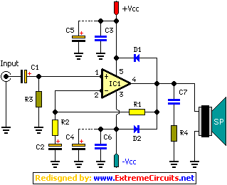
This project features a 2 x 18W Hi-Fi Stereo Power Amplifier, utilizing two TDA2030 integrated circuits. The design incorporates excellent input sensitivity, minimal distortion, dependable operational stability, and comprehensive protection against overloads and short-circuits. It's suitable for boosting existing small audio systems or driving an additional set of speakers alongside those already connected. The circuit demands a balanced power supply of ±18Vdc with a current capacity of 3A. It can handle loads ranging from 4 to 8 ohms. A substantial heat sink is necessary for this configuration. The displayed diagram illustrates only the left channel; creating mirrored versions will achieve a stereo effect.
TDA2030 Integrated Circuit
The TDA2030 is a dual channel audio power amplifier IC. It's a popular choice for building stereo amplifiers due to its high power output, low distortion characteristics, and built-in protection features. These ICs are typically packaged in a DIP (Dual Inline Package) format, making them relatively easy to integrate into electronic circuits. They're known for their efficiency and reliability, contributing to the overall performance of the amplifier circuit.
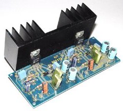
Picture of the project:
Circuit Diagram:
Parts:
- R1 = 22K
- R2 = 680R
- R3 = 22K
- R4 = 1R-1w
- D1 = 1N4001
- D2 = 1N4001
- C1 = 1uf-25V
- C2 = 22uF-25V
- C3 = 100nF-63V
- C4 = 100nF-63V
- C5 = 100uF-25V
- C6 = 100uF-25V
- C7 = 220nF-63V
- IC = TDA2030
If it does not work:
- Verify the assembly for potential intermittent connections, bridging across adjacent traces, or soldering flux residue, which frequently causes issues.
- Re-examine all external connections to and from the circuit for any errors.
- Confirm that all components are present and positioned correctly.
- Ensure all polarized components have been mounted with the correct polarity.
- Verify that the supply provides the correct voltage and is connected with the proper orientation for the circuit.
- Inspect the project for defective or damaged components.
Technical Specifications:
- Supply voltage = ±18Vdc/3A symmetrical (see text)
- Current consumption = 3A maximum
- Input impedance = 500K Ohms
- Input sensitivity = 250 mV
- Signal to noise ratio = 80 dB
- Frequency response = 20 - 20,000 Hz ± 1 dB
- Distortion = 0.5 % maximum
- Load impedance = 4 - 8 ohm

