- Water Pump Relay Circuit: Build Your 12V Control System
- Plant Watering Circuit: Build Your Smart Sensor!
- Automatic Water Tank Level Control Circuit Diagram
- DIY Water Level Monitor: Build Your Smart Tank Circuit
- Water Level Alert Circuit: Build Your Own
- Water Leak Detection Circuit Diagram 4093 Alarm
- Build Your Rain Detector Circuit – 1N4001 & C106B1
- Salt Percentage Indicator Circuit Diagram
- Build a Smart Plant Watering System with a 3V Circuit
Build Your Rain Detector Circuit – 1N4001 & C106B1
Description
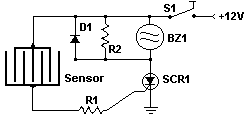
This circuit employs a detector constructed from a diminutive, laser-cut printed circuit board and a straightforward Silicon Controlled Rectifier (SCR) circuit to monitor rainfall and trigger a buzzer. The SCR can additionally be utilized to activate a relay, illuminate a light, or transmit a signal to a surveillance system.
Circuit diagram
Parts
- R1 1K 1/4 W Resistor
- R2 680 Ohm 1/4 W Resistor
- D1 1N4001 Silicon Diode
- BZ1 12V Buzzer
- S1 SPST Switch
- SCR1 C106B1 SCR 106CY
- SENSOR See Notes
- MISC Board, Wire, Case, PC Board (For Sensor)
Notes
- The sensor is a compact piece of printed circuit board engraved according to the design illustrated in the schematic. The traces must be held extremely close together, but never in contact. A large spiral design would also be suitable.
- Ensure a sufficiently loud buzzer is utilized.
Integrated Circuit Details
The C106B1 SCR 106CY is a commonly used Silicon Controlled Rectifier. This device acts as an electronic switch, controlling current flow based on a gate signal. When the gate signal is applied, the SCR conducts current, even if the anode is reverse-biased. Once triggered, the SCR remains conducting until the gate signal is removed, or the anode current falls below a specific threshold. This characteristic makes it ideal for switching applications such as controlling motors, switching relays, and implementing logic circuits. The device's performance is significantly influenced by its junction temperature, and proper heat sinking may be necessary for higher-current applications. This specific SCR operates with a maximum continuous collector current of 1 Amp and a peak repetitive reverse insulating voltage of 60V.
