- Water Pump Relay Circuit: Build Your 12V Control System
- Plant Watering Circuit: Build Your Smart Sensor!
- Automatic Water Tank Level Control Circuit Diagram
- DIY Water Level Monitor: Build Your Smart Tank Circuit
- Water Level Alert Circuit: Build Your Own
- Water Leak Detection Circuit Diagram 4093 Alarm
- Build Your Rain Detector Circuit – 1N4001 & C106B1
- Salt Percentage Indicator Circuit Diagram
- Build a Smart Plant Watering System with a 3V Circuit
Water Leak Detection Circuit Diagram 4093 Alarm
Description
Have you ever witnessed the transformation of the staircase leading to an upper floor into a waterfall, or perhaps observed your aquarium fish attempting to swim across the carpet? We sincerely hope not, as the consequences are typically quite dramatic. With a selection of electronic components, you can at least ensure you are warned before needing to put on waterproof boots. It’s preferable to prevent water issues rather than addressing them afterward. Despite the numerous precautions taken, occasional leaks can still occur.
A burst water supply hose for the washing machine, an unclosed bath tap, a cracked aquarium wall, or a leaking boiler or central heating tank – possibilities abound. In such scenarios, it’s beneficial to be notified as quickly as feasible, for instance, through an acoustic water alarm. This allows you to minimize potential damage. If you are proficient in soldering and distinguish between an integrated circuit and a personal computer, you will likely enjoy constructing the electronic water alarm detailed herein.
The circuit leverages the fact that water, even seemingly pure, naturally contains some level of conductivity, enabling it to conduct electricity to a degree. It’s built around a well-established integrated circuit from the older 4000-series logic family: the 4093. This IC comprises four inverted-output AND gates (NAND gates) incorporating Schmitt-trigger inputs. When water is detected between the probes, it produces an intermittent and somewhat annoying beeping sound.
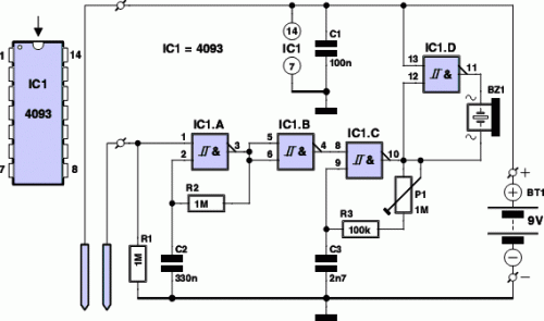
Circuit diagram:
The conductivity of the water is utilized to activate the circuit surrounding IC1a. The two electrodes (probes) are positioned at the lowest point where water is anticipated to accumulate. They can be fashioned from tinned copper wires, alternatively, two sections of circuit board with the copper surface coated in solder can be employed. The combination of IC1a, resistor R2, and capacitor C2 forms a simple oscillator that generates the intermittent (on/off) effect of the alarm. When no water is present between the probes, the input of IC1a is maintained low by R1, and the output of IC1b remains low as well.
The oscillator is inactive in this state. When moisture is sensed, the power supply voltage pulls input 1 of gate IC1a high via the conductive water, causing the gate to begin oscillating. Whenever the output of IC1b is high, the tone generator incorporating IC1c is enabled, and subsequently, it energizes buzzer BZ1. The resulting effect is a periodic, intermittent beeping sound. You can adjust the intermittent nature of the sound produced by the water alarm to suit your preferences by modifying the value of R2 or C2. You can also adjust the pitch of the sound using P1.
The closer the pitch approximates the resonant frequency of buzzer BZ1, the louder the tone will be. It is advisable to set the sound to the most intrusive level possible. Gate IC1d is used to amplify the amount of power delivered to the buzzer. It inverts the output signal from IC1c, thereby doubling the voltage applied to the buzzer. Naturally, the circuit of the alarm must be installed in a location that remains dry. Utilize a pair of thin, twisted wires to connect the electrodes (probes) to the board. Naturally, you should employ insulated, flexible wire for this purpose.
Twisting the wires together reduces the sensitivity of the relatively long connection between the probes and the circuit to false alarms due to external electromagnetic interference. The current consumption is very low (less than 0.1µA) when everything is dry. When the buzzer is energized, the current consumption can rise to approximately 2mA. We measured 3mA with the frequency set to its maximum value. The battery will therefore last for several years as long as no water is detected. However, you should bear in mind that the battery may begin to leak after an extended period…
circuit from http://www.extremecircuits.net/2010/04/water-alarm-circuit-diagram.html
