- Water Pump Relay Circuit: Build Your 12V Control System
- Plant Watering Circuit: Build Your Smart Sensor!
- Automatic Water Tank Level Control Circuit Diagram
- DIY Water Level Monitor: Build Your Smart Tank Circuit
- Water Level Alert Circuit: Build Your Own
- Water Leak Detection Circuit Diagram 4093 Alarm
- Build Your Rain Detector Circuit – 1N4001 & C106B1
- Salt Percentage Indicator Circuit Diagram
- Build a Smart Plant Watering System with a 3V Circuit
Water Pump Relay Circuit: Build Your 12V Control System
Description
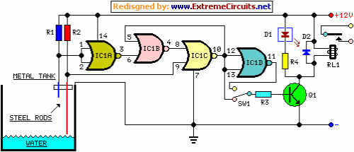
Utilizing a Relay to manage a water pump, this circuit facilitates automatic water level control for a reservoir or well. The shorter metallic rod serves as the “water high” sensor, while the longer one is the “water low” sensor. When the water level drops beneath both sensors, IC1C’s output (pin #10) is inactive; however, if the water makes contact with the longer sensor, the output remains inactive until the shorter sensor is engaged. At this point, IC1C’s output becomes active, Q1 conducts, and the Relay is energized, initiating pump operation.
As the water level diminishes, the shorter sensor ceases to interact with the water, yet IC1C’s output remains active due to the signal returning to pin #5 of IC1B, therefore the pump continues its operation. Nevertheless, when the water level decreases below the longer sensor, IC1C’s output becomes inactive, and the pump ceases to function. SW1 is optional and implemented to provide reversed operation. Activating SW1 by connecting R3 to pin #11 of IC1D, the pump will operate when the reservoir is nearly depleted and will halt when the reservoir is full. In this configuration, the pump will be used to fill the reservoir and not to empty it, as in the default operational mode.
Circuit diagram:
Parts:
- R1 = 15K - 1/4W Resistors
- R2 = 15K - 1/4W Resistors
- R3 = 10K - 1/4W Resistor
- R4 = 1K - 1/4W Resistor
- D1 = LED - any type and color
- D2 = 1N4148 - 75V 150mA Diode
- Q1 = BC337 - 45V 800mA NPN Transistor
- IC1 = 4001 Quad 2 Input NOR Gate CMos IC
- SW = SPDT Toggle or Slide Switch (Optional)
- RL1 = Relay with SPDT 2A @ 230V switch
- Coil Voltage 12V - Coil resistance 200-300 Ohm
- Two steel rods of appropriate length
Notes:
- The two steel rods must be supported by a small insulated (wooden or plastic) board.
- The circuit can be employed also with non-metal tanks, provided a third steel rod having approximately the same height of the tank will be added and connected to the circuit’s negative ground.
Integrated Circuit Details
IC1 is a 4001 Quad 2 Input NOR Gate CMos IC. This IC is a versatile component utilized for digital logic implementation. The 4001 provides four independent NOR gates, enabling complex logic circuits to be designed. Each gate accepts two inputs and produces one output. The CMos technology ensures low power consumption and high noise immunity, making it suitable for a wide range of applications, including level detection, signal gating, and control circuits. The NOR gate function is particularly useful in this circuit to control the pump based on the water level sensor readings.
