- Water Pump Relay Circuit: Build Your 12V Control System
- Plant Watering Circuit: Build Your Smart Sensor!
- Automatic Water Tank Level Control Circuit Diagram
- DIY Water Level Monitor: Build Your Smart Tank Circuit
- Water Level Alert Circuit: Build Your Own
- Water Leak Detection Circuit Diagram 4093 Alarm
- Build Your Rain Detector Circuit – 1N4001 & C106B1
- Salt Percentage Indicator Circuit Diagram
- Build a Smart Plant Watering System with a 3V Circuit
Salt Percentage Indicator Circuit Diagram
Determines the approximate concentration of dissolved salts within aqueous solutions
Three-segment LED indicator
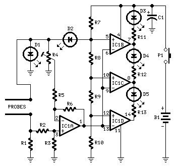
Circuit diagram
Parts:
- R1 470R 1/4W Resistor
- R2, R5 10K 1/4W Resistors
- R3, R6 220K 1/4W Resistors
- R4 5K 1/2W Trimmer Cermet
- R7 680R 1/4W Resistor
- R8 2K2 1/4W Resistor
- R9, R10, R11, R12, R13 1K 1/4W Resistors
- C1 100µF 25V Electrolytic Capacitor
- D1, D2, D3 3 or 5mm. Red LEDs
- D4 3 or 5mm. Green LED
- D5 3 or 5mm. Yellow LED
- IC1 LM324 Low Power Quad Operational Amplifier
- P1 SPST Pushbutton
- Probes (See Text)
- B1 9V PP3 Battery
- Clip for PP3 Battery
Device purpose:
This circuit was designed to roughly estimate the percentage of salts present in liquid samples. With appropriate adjustments, it can provide a quick and approximate assessment of salt levels in foods and other liquid substances for dietary monitoring and related applications.
Circuit operation:
IC1A, an operational amplifier, is configured as a DC differential amplifier, with its output voltage increasing as the DC resistance measured by the probes decreases. Pure water typically exhibits a high DC resistance, and this resistance will diminish proportionally as salt content rises. IC1B, IC1C, and IC1D are arranged as comparators, driving the LEDs D5, D4, and D3 respectively, as the voltage at their inverting inputs increases. Consequently, no LED will activate when the salt content is low; the yellow LED D5 illuminates when the salt level is low, the green LED D4 turns on when the salt content is considered normal, and the red LED D3 indicates a high salt concentration. D1 and D2 continually remain active, supplying two reference voltages through the reference resistor chain R8, R9, and R10. This configuration enhances the circuit’s accuracy. The 3.2V supply feeds the non-inverting inputs of the comparators via resistor R8, while the 1.6V reference voltage provided by D1 powers the probes and the trimmer resistor R4. One of the red LEDs can be used as an indicator light to signal when the device is operational.
Probes:
- Experimental results demonstrated that a simple and cost-effective probe can be constructed utilizing a 6.3mm mono jack plug. The probe's two leads are connected to the circuit inputs using a two-wire shielded cable.
- The jack’s metal body is formed from two sections of differing lengths, separated by a black plastic ring. It is recommended to cover the longer section with insulating tape to create an exposed metal surface of similar length to the tip portion (approximately 8 to 10mm) beginning from the black plastic ring.
- In the prototype, three tablespoons of liquid were introduced into a cylindrical plastic cap with a height of 55mm and a diameter of 27mm. The metal part of the jack probe was then immersed in the liquid.
Notes:
- Allow at least 30 seconds for a stable reading.
- Thoroughly clean and wipe the probe after each test.
- To fine-tune the circuit and achieve a more precise reading, you may use a DC voltmeter in the 10V range to measure the voltage across pin #1 of IC1A and the negative supply.
- Adjust R4 to obtain a zero reading on the voltmeter when the probe is inserted into fresh water.
- Modify R8 to adjust the range of D4, and modify R9 to adjust the range of D5 as desired.
- The P1 pushbutton can be replaced with a standard SPST switch.
circuit from http://www.redcircuits.com/
