- Water Pump Relay Circuit: Build Your 12V Control System
- Plant Watering Circuit: Build Your Smart Sensor!
- Automatic Water Tank Level Control Circuit Diagram
- DIY Water Level Monitor: Build Your Smart Tank Circuit
- Water Level Alert Circuit: Build Your Own
- Water Leak Detection Circuit Diagram 4093 Alarm
- Build Your Rain Detector Circuit – 1N4001 & C106B1
- Salt Percentage Indicator Circuit Diagram
- Build a Smart Plant Watering System with a 3V Circuit
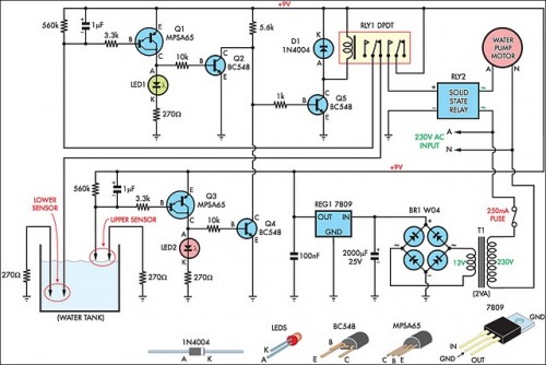
Automatic Water Tank Level Control Circuit Diagram
Description
This circuit has proven remarkably effective in supplying a reticulated water system for agricultural operations. Eight troughs are serviced across various fields, where inadequate water availability could pose significant risks to livestock. Previously, the reservoir was manually filled using a timed control system, but this approach ultimately failed. During periods of elevated temperatures, the herd would deplete the reservoir regularly, resulting in extended water shortages or overflow incidents if accompanied by precipitation and reduced cattle consumption.
Circuit Diagram:
The system designed utilizes a 3HP submersible well pump, characterized by a substantial initial current draw, requiring a robust solid-state relay capable of handling the startup load. Two Darlington transistors, Q1 & Q3, alongside Q2 & Q4, are arranged to interact with the upper and lower water level detectors situated within the tank. Q2 & Q4 incorporate a 5.6kOhm load resistor and function as a NOR gate. The output from this gate subsequently activates Q5, triggering the operation of relay RLY1.
When the water level is at a low point, both detectors will be open, leading to a high output from the NOR gate, and consequently, the relay is energized. This action causes the normally closed (NC) contacts of RLY1 to open, disconnecting the lower detector. However, the upper detector remains open-circuit, maintaining the NOR gate's output at a high level and keeping the relay engaged. The normally open (NO) contact of the relay is then utilized to power the solid-state relay RLY2, initiating pump operation.
This situation persists until the water reaches the maximum level, which then reduces the NOR gate’s output to 0V, disabling relay RLY1 and ceasing pump activity. In practice, the upper sensor is positioned slightly below the tank's overflow point, while the lower sensor is positioned approximately halfway up the tank. The sensor contacts consist of two stainless steel screws, approximately 25mm apart, screwed through the plastic tank walls. The electrical connections at the tank’s exterior are protected by neutral-cure silicone sealant.
Solid-State Relays
Solid-state relays (SSRs) are electronic switches used to control high-current circuits using a low-current control circuit. RLY2, the solid-state relay used in this circuit, is designed to switch the 3HP pump’s power, handling the high inrush current associated with pump starts. Unlike mechanical relays, SSRs have no moving parts, offering increased reliability and faster switching speeds. They typically utilize semiconductor devices like MOSFETs or IGBTs to achieve switching, allowing for faster response times and reduced wear and tear. These features are crucial for managing the high-demand startup of the submersible well pump, ensuring efficient and dependable operation of the water delivery system.
Relays
Relays, specifically RLY1 and RLY2, are electromechanical switches that allow a low-current signal to control a high-current circuit. Relay RLY1 is an electromagnetic relay that acts as the primary control switch, while RLY2 is a solid-state relay. RLY1 is responsible for initiating and terminating pump operation based on water level readings. The design incorporates two Darlington transistors, Q1 & Q3, along with Q2 & Q4, configured as a NOR gate. This arrangement provides a robust switching mechanism, guaranteeing reliable control of the pump. The use of relays is essential due to the system’s requirement to manage a substantial power load with a relatively small control signal, which relays facilitate effectively.
