- 700Hz Pulse Generator & Signal Tracer Circuit
- Build Your Own 66 Melody Generator Circuit Diagram
- Build Your Own 9V Surf Noise Simulator
- Build Your Own Music: UM66 Circuit Diagram (8 Ohm)
- Build Your Powerful 5-Tone Siren Circuit Diagram
- Cuckoo Song Generator: 667Hz & 545Hz
- DIY Bell Tone Generator Circuit Schematic
- Cricket Chirp Generator Circuit: Build Your Realistic Sound
- Build a 4-Tone Siren Circuit with One IC
- Build Your Own Electronic Canary: Circuit Diagram & Chirp Secrets
- Build Your 8 Sound Effects Generator with HT2884
- UM3561 Sound Effects Generator Circuit Diagram - Build Your Own!
- Low Distortion Audio Sine Wave Oscillator Circuit Diagram
- Cuckoo Sound Generator: Build Your Own Realistic Bird Song
- Dual Tone Siren Circuit Diagram – Build Your Own!
Build Your 1kHz Tone Generator with a 555 Timer
Description
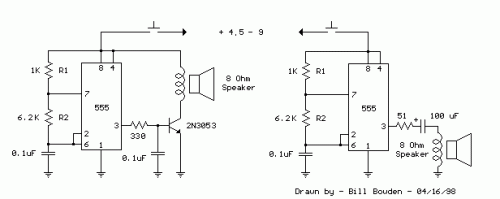
This schematic demonstrates a fundamental 555 square wave generator, designed to yield a 1 kHz audio signal directed towards a 8 ohm speaker. Within the depicted circuit on the left, the loudspeaker is separated from the timing circuit via a NPN power transistor, offering increased current capability exceeding what’s achievable directly from the 555 timer (maximum = 200 mA). A small capacitor is strategically placed at the transistor’s base, which moderates switching speeds and minimizes the inductive voltage generated by the speaker. The frequency is approximately 1.44/(R1 + 2*R2)*C, where R1 (1k) is considerably smaller than R2 (6.2k) to achieve a nearly square waveform. To achieve lower frequencies, the value of R2 can be amplified, while higher frequencies may necessitate a smaller capacitor, as reductions in R1 below 1k are typically limited. Reduced volume levels can be attained by incorporating a small resistor in series with the speaker, typically ranging from 10 to 100 ohms.
555 Timer
The 555 timer is an integrated circuit (IC) that is widely used as a timing circuit. It comes in several packages, including DIP, SOIC, and SMD. It is a versatile chip that can be configured as an oscillator, timer, or flip-flop. The 555 timer is a three-terminal IC that can be powered from a wide range of voltages. It has three main pins: TRIGGER, OUTPUT, and RESET. The OUTPUT pin provides the timing signal, while the TRIGGER pin is used to start the timer. The RESET pin is used to reset the timer.
