- 12V Motor Speed Controller/Dimmer Circuit Design
- DC Motor Speed Controller: 1.4V Variable Voltage Circuit
- Discrete 8-Bit PWM Generator Circuit Design
- Stepper Motor Drive with TDA2030 Circuit Design
- Varying Brightness AC Lamp Circuit Design
- DIY Temperature-Controlled Soldering Iron Circuit Diagram 400°C
- Unipolar Stepper Motor Driver Circuit Diagram
- Build Your Own Fan Control
- 12V DC Motor Control Circuit: Build Your Own!
- Variable Power Controller with 555 Timers
- 555 PWM Speed Control: Circuit Diagram & Explanation
- Pulse Width Modulation DC Motor Control: A Simple 6V Circuit
- Build Your Own Stepper Motor Controller Circuit 1K
Pulse Width Modulation DC Motor Control: A Simple 6V Circuit
Description
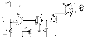
Frequently, individuals attempt to regulate DC motors utilizing a variable resistor or a variable resistor coupled with a transistor. Although the latter method proves effective, it generates heat, consequently leading to energy loss. This straightforward pulse width modulation DC motor control system successfully avoids these complications. It adjusts the motor’s rotation rate by supplying the motor with brief bursts of current. These bursts of current vary in length to alter the motor’s speed. Increased burst durations result in faster motor rotation, while reduced durations cause slower rotation, conversely.
Circuit diagram
Parts
- R1 1 Meg 1/4W Resistor
- R2 100K Pot
- C1 0.1uF 25V Ceramic Disc Capacitor
- C2 0.01uF 25V Ceramic Disc Capacitor
- Q1 IRF511 MOSFET or IRF620
- U1 4011 CMOS NAND Gate
- S1 DPDT Switch
- M1 Motor (See Notes)
- MISC Case, Board, Heatsink, Knob For R2, Socket For U1
Notes
- R2 modifies the oscillator’s frequency, and consequently, the speed of M1.
- M1 can be any DC motor operating at 6V and not drawing more than the maximum current of Q1. Voltage amplification can be achieved by connecting a higher voltage to the switch instead of the 6V that powers the oscillator. Ensure that the power rating of Q1 is not surpassed if this is done.
- Q1 requires a heatsink to dissipate heat.
- Q1 in the parts list can handle a maximum of 5A. For higher current requirements, consider utilizing the IRF620, which can manage up to 6A.
More about components
The 4011 CMOS NAND Gate (U1) is a versatile digital logic component. This integrated circuit implements four independent NAND gates, enabling a wide range of digital functions. NAND gates are fundamental building blocks in digital circuits, used for logic operations such as AND, OR, and NOT. Its small size and low power consumption make it suitable for various applications, including motor control and digital signal processing. The gate’s four inputs and two outputs provide flexibility in designing digital circuits.
