- 12V Motor Speed Controller/Dimmer Circuit Design
- DC Motor Speed Controller: 1.4V Variable Voltage Circuit
- Discrete 8-Bit PWM Generator Circuit Design
- Stepper Motor Drive with TDA2030 Circuit Design
- Varying Brightness AC Lamp Circuit Design
- DIY Temperature-Controlled Soldering Iron Circuit Diagram 400°C
- Unipolar Stepper Motor Driver Circuit Diagram
- Build Your Own Fan Control
- 12V DC Motor Control Circuit: Build Your Own!
- Variable Power Controller with 555 Timers
- 555 PWM Speed Control: Circuit Diagram & Explanation
- Pulse Width Modulation DC Motor Control: A Simple 6V Circuit
- Build Your Own Stepper Motor Controller Circuit 1K
DIY Temperature-Controlled Soldering Iron Circuit Diagram 400°C
Description
A significant factor contributing to the higher cost of professional soldering stations is the requirement for soldering irons incorporating built-in temperature sensors, such as thermocouples. This circuit obviates the need for a specialized sensor; instead, it senses the temperature of the soldering iron’s heating element directly from its resistance. Consequently, the circuit should, in principle, function with any iron whose resistance varies predictably and positively with temperature (i.e., possesses a positive temperature coefficient).
DC-DC Converter
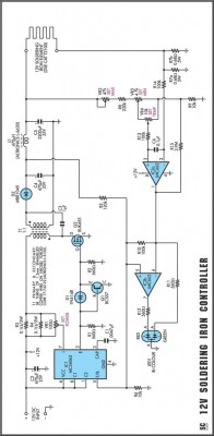
A DC-DC converter is central to this circuit’s operation. Specifically, components IC1, Q1, D1, Q2, T1, and D2, alongside inductor L1, are integrated into this converter. This converter elevates the initial 12V DC input to approximately 16V. The increased voltage provides a boost in power to the iron, consequently reducing the time required for the iron to reach its operating temperature. This enhanced output voltage is then applied to a resistance bridge, wherein the heating element of the iron constitutes one leg of the bridge.
The other elements within the bridge include resistors R7-R9 and potentiometers VR2-VR4. Upon the soldering iron attaining the pre-set temperature, dictated by VR4, the output of IC2a goes high, sending a signal to the switching regulator IC1. This action forces the output voltage of the converter to a comparatively lower level. A bi-colour LED signals that the iron has achieved the desired maximum temperature by transitioning from red to green. The iron subsequently cools until it falls below the preset temperature, at which point the output voltage from the DC-DC converter returns to its higher level, and the cycle repeats.
A degree of hysteresis is incorporated into the circuit, causing the LED to flicker between red and green while the iron maintains its set temperature. Calibrate the circuit following this procedure: while the iron remains relatively cold, monitor the input voltage and current and adjust VR1 so that the input power (Volts x Amps) is approximately 50W. After completing this adjustment, set VR4 to its maximum position and adjust VR2 so that the LED flickers between red and green when the iron reaches the desired maximum temperature.
Finally, set VR4 to a mid-position and adjust VR3 so that the LED flickers when the iron reaches the desired mid-range operating temperature. For example, you might choose to set the maximum temperature to about 400°C and the mid-range operating temperature to approximately 350°C. The resultant overall temperature range, in this instance, should be roughly 280°C to 400°C. Verify the calibration and repeat the adjustment procedure if any corrections are needed. Utilize a temperature probe, preferably one specifically designed for soldering irons, rather than relying on guesswork when making the adjustments.
Circuit diagram:
The remaining components of the bridge include resistors R7-R9 and potentiometers VR2-VR4.
A degree of hysteresis built into the circuit makes the LED flicker between red and green while the iron is maintained at its preset temperature. Calibrate the circuit as follows: while the iron is still relatively cold, monitor the input voltage and current and adjust VR1 so that the input power (Volts x Amps) is about 50W. When you have done that, set VR4 to maximum and adjust VR2 so that the LED flickers between red and green when the iron has reached the desired maximum temperature.
Finally, set VR4 to mid-position and adjust VR3 so that the LED flickers when the iron reaches the desired mid-range operating temperature. As an example, you might choose to set the maximum temperature to about 400°C and the mid-range operating temperature to about 350°C. The overall temperature range, in that case, should be approximately 280°C to 400°C. Check that the calibration is correct and repeat the adjustment procedure if necessary. Use a temperature probe, preferably one designed especially for soldering irons, rather than guesswork, when making the adjustment.
Note:
VR4 should possess a logarithmic taper to compensate for non-linearity in the temperature-resistance characteristic of the soldering iron.
circuit from http://www.extremecircuits.net/2010/05/temperature-controlled-soldering-iron.html
