- 12V Motor Speed Controller/Dimmer Circuit Design
- DC Motor Speed Controller: 1.4V Variable Voltage Circuit
- Discrete 8-Bit PWM Generator Circuit Design
- Stepper Motor Drive with TDA2030 Circuit Design
- Varying Brightness AC Lamp Circuit Design
- DIY Temperature-Controlled Soldering Iron Circuit Diagram 400°C
- Unipolar Stepper Motor Driver Circuit Diagram
- Build Your Own Fan Control
- 12V DC Motor Control Circuit: Build Your Own!
- Variable Power Controller with 555 Timers
- 555 PWM Speed Control: Circuit Diagram & Explanation
- Pulse Width Modulation DC Motor Control: A Simple 6V Circuit
- Build Your Own Stepper Motor Controller Circuit 1K
Build Your Own Stepper Motor Controller Circuit 1K
Description
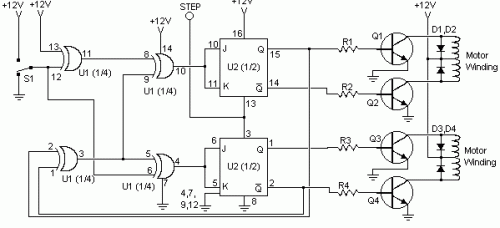
A circuit was discovered within archived files. Its origin remains unknown, though it’s believed to have originated from “The Robot Builder’s Bonanza”, authored by Gordan McComb. The creator considered the design reasonably practical and elected to share it here. The circuit design presents a straightforward and affordable solution. This characteristic is particularly beneficial, considering the substantial costs associated with many commercially available stepper motor control integrated circuits. This circuit is constructed utilizing readily accessible components, allowing for uncomplicated adaptation to computer-based control systems. Utilizing economical surplus transistors and a stepper motor, the overall cost of the circuit can be maintained below $10.Circuit diagram
Parts
- R1, R2, R3, R4 - 1K 1/4W Resistor
- D1, D2, D3, D4 - 1N4002 Silicon Diode
- Q1, Q2, Q3, Q4 - TIP31 NPN Transistor (See Notes) or TIP41, 2N3055
- U1 - 4070 CMOS XOR Integrated Circuit
- U2 - 4027 CMOS Flip-Flop
- S1 - SPDT Switch
- MISC - Case, Board, Wire, Stepper Motor
Notes
- Standard (2N3055, etc.) power transistors can be substituted for Q1-Q4 without difficulty.
- Each time the STEP line is activated, the motor advances one increment.
Integrated Circuits Description
The 4070 CMOS XOR Integrated Circuit (U1) is a versatile digital logic component. This IC is fabricated on a silicon substrate and is designed to implement XOR (Exclusive OR) logic functions. It's known for its small size, low power consumption, and relatively high operating speed. It’s frequently employed in digital circuits, signal processing, and control systems where logic gates are required. Its integration allows for compact design and efficient operation.
Integrated Circuits Description
The 4027 CMOS Flip-Flop Integrated Circuit (U2) is a fundamental building block in digital electronics. This IC is created using a semiconductor material, typically silicon, and acts as a basic memory element. It’s designed to store one bit of information, either a 0 or a 1. The flip-flop consists of interconnected transistors that allow the stored state to be retained until a new input signal changes the state. Its function is central to creating memory circuits, shift registers, and other digital systems. Its design leverages the properties of transistors to achieve reliable data storage.
Warnings
Please exercise caution when working with electrical circuits. Incorrect wiring or operation can result in electrical shock or equipment damage. Always disconnect power before making any modifications. This circuit diagram is provided as-is, and the author assumes no liability for any damages or injuries resulting from its use. Always ensure proper grounding and adhere to relevant safety regulations.
Author and Source
Circuit diagram created by [Name of Creator] - Source: Archived Files
