- 12V Motor Speed Controller/Dimmer Circuit Design
- DC Motor Speed Controller: 1.4V Variable Voltage Circuit
- Discrete 8-Bit PWM Generator Circuit Design
- Stepper Motor Drive with TDA2030 Circuit Design
- Varying Brightness AC Lamp Circuit Design
- DIY Temperature-Controlled Soldering Iron Circuit Diagram 400°C
- Unipolar Stepper Motor Driver Circuit Diagram
- Build Your Own Fan Control
- 12V DC Motor Control Circuit: Build Your Own!
- Variable Power Controller with 555 Timers
- 555 PWM Speed Control: Circuit Diagram & Explanation
- Pulse Width Modulation DC Motor Control: A Simple 6V Circuit
- Build Your Own Stepper Motor Controller Circuit 1K
Variable Power Controller with 555 Timers
Disclaimer Please take the greatest of care in handling AC mains supply while constructing this project. If you have no knowledge of mains wiring or unfamiliar with household mains supply, PLEASE DO NOT ATTEMPT CONSTRUCTION. I take no responsibility in any personal injury or loss of life or properties suffered by any person while undertaking the construction of this project or using the end product by following my instructions.
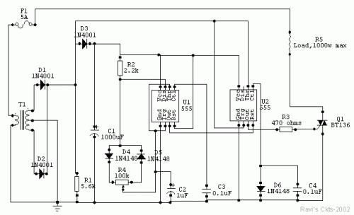
Circuit diagram
About the Circuit
This circuit is built around two 555 timer ICs, U1 and U2. U1 is configured as a variable duty cycle oscillator with a constant time period of approximately 0.1 second. The duty cycle can be varied from 0 to 100 percent by the linear potentiometer R4, which is mounted on the front portion of the enclosure with a marked dial indicating power levels from 0 to 100 percent in 5 percent intervals. The output of U1 (pin 3) is connected to the non-inverting input (pin 4) of U2.
U2 is wired as a comparator with hysteresis, also known as a Schmitt trigger. Diode D6 provides a reference voltage at the control voltage (pin 5) terminal, establishing a stable potential of 0.7V. The threshold (pin 6) and trigger (pin 2) terminals are interconnected, forming the input of the Schmitt trigger. The output (pin 3) of the Schmitt trigger activates high when the input voltage falls below 0.35V and remains high until it exceeds 0.7V.
Transformer T1 provides unidirectional AC voltage across R1 with a peak voltage of 8.5V and a frequency of 100Hz. Capacitor C1 acts as a filtering component. Diode D3 prevents the voltage across R1 from being completely filtered by C1.
Since the input of the Schmitt trigger is connected across R1, the output will be high when the input voltage drops below 0.35V and remains high until it rises above 0.7V. If pin 4 of U2 remains unconnected, the triac will be triggered at the beginning of each AC half-cycle by a short pulse, delivering full power to the load. However, because the output of U1 is connected to the non-inverting input of U2, the Schmitt trigger generates pulses to the gate of the triac only when the output of U1 is high. This mechanism enables the achievement of variable duty cycle zero-crossing switching. A 5-amp triac, capable of switching loads up to 1000W, is employed. Increasing the size of the heat sink is necessary when operating with larger loads.
Construction
This circuit can be constructed on a general-purpose IC stripboard. Potentiometer R4 should be a linear potentiometer with a plastic shaft, mounted on the front portion of the enclosure, with a marked dial indicating power levels from 0 to 100 percent in 5 percent intervals. If a metallic enclosure is utilized, careful attention must be paid to ensure that the heat sink of the triac does not contact the enclosure anywhere.
To prevent electric shock, do not touch any part of the circuitry while it is in operation.
Parts
- U1 & U2 - NE555 timer IC
- Q1 - 5A, 400 PIV triac (BT136)
- D1-D3 - IN4001 rectifier diodes
- D4-D6 - IN4148 switching diodes
- R1 - 5.6K
- R2 -2.2K
- R3 -470 ohms
- R4 - 100K linear potentiometer with plastic shaft
- (all resistors ¼ watt, 5% tolerance)
- C1 - 1000mfd, 12V
- C2 - 1mfd, 12V
- C3,C4 - 0.1mfd,50V ceramic
- T1 - 220V primary 6V-0-6V secondary, 150ma
- F1 - 5-amp fuse
- (You will have to connect the AC line to T1 primary. I have not shown that)
circuit from http://www.electronics-lab.com/
