- 12V Motor Speed Controller/Dimmer Circuit Design
- DC Motor Speed Controller: 1.4V Variable Voltage Circuit
- Discrete 8-Bit PWM Generator Circuit Design
- Stepper Motor Drive with TDA2030 Circuit Design
- Varying Brightness AC Lamp Circuit Design
- DIY Temperature-Controlled Soldering Iron Circuit Diagram 400°C
- Unipolar Stepper Motor Driver Circuit Diagram
- Build Your Own Fan Control
- 12V DC Motor Control Circuit: Build Your Own!
- Variable Power Controller with 555 Timers
- 555 PWM Speed Control: Circuit Diagram & Explanation
- Pulse Width Modulation DC Motor Control: A Simple 6V Circuit
- Build Your Own Stepper Motor Controller Circuit 1K
555 PWM Speed Control: Circuit Diagram & Explanation
The 555 is frequently utilized and can be employed for uncomplicated PWM speed regulation
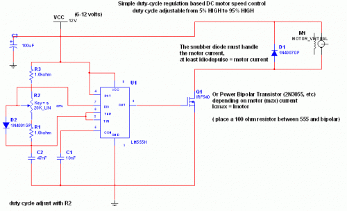
Circuit Diagram
Circuit Explanation:
The 555 IC is configured as an astable arrangement, and the frequency remains constant regardless of the duty cycle. This is due to the consistent total resistance (R charge + R discharge, noting the diode) which is equal to 22Kohm, producing a frequency of approximately 1Khz. A noticeable hum is present. When the potentiometer is fully up, the Rcharge resistance is 1,0 Kohm (the diode prevents the capacitor from charging through the second potentiometer section and the other 1,0 Kohm resistor), and Rdischarge is 21 Kohm, resulting in a 5% duty cycle and a 1Khz frequency. When the potentiometer is fully down, the Rcharge resistance is 21,0 Kohm (the diode prevents the capacitor from charging through the second potentiometer section and the other 1,0 Kohm resistor), and Rdischarge is 1 Kohm, yielding a 95% duty cycle and a 1Khz frequency. When the potentiometer is set to 50%, the Rcharge resistance is 11,0 Kohm (the diode prevents the capacitor from charging through the second potentiometer section and the other 1,0 Kohm resistor), and Rdischarge is 11 Kohm, creating a 50% duty cycle and a 1Khz frequency. The 555 offers considerable current capabilities suitable for efficiently driving both the MOSFET and the bipolar transistor. I actually implement this system to power the DC motor of my small Rotary spark gap Tesla coil at variable speed. If you find the 1Khz hum produced by the motor objectionable, consider increasing the frequency beyond the audible range by replacing the potentiometer, but bear in mind that at higher frequencies, the inductive reactance of the motor increases, leading to a drop in efficiency.
Important:
Clearly, the MOSFET (or bipolar) must possess sufficient current-carrying capacity to effectively drive the motor; therefore, the drain (or collector) current should correspond to the maximum motor current under the power supply voltage when the motor is de-energized. The snubber diode is also critical, as it short-circuits the motor during the off cycle. Both the MOSFET (or bipolar) and diode require proper attachment (if you wish to prevent their failure ;-) ) to a heatsink. If the maximum motor current exceeds 100 or 200mA, it’s advisable to avoid excessively stressing the motor, as it can lead to overheating of the motor, transistor, and diode. To prevent braking during the off cycle, incorporate a resistor in series with the snubber diode. This will marginally improve efficiency while also increasing the motor's inertia when slowing down. The value of the resistor should be calculated as R = V(breakdown transistor) / Imax, and the power dissipation should be 5W. MOSFETs include internal zener diodes, but do not rely on them ;-)
circuit from http://www.electronics-lab.com/
