- Long Delay Timer Circuit: 35 Minute Battery-Powered Design
- Build Your Custom 3-9 Minute Beep Timer Circuit
- Build Your Amplifier Timer Circuit – 15 Minute Delay
- Timed Beeper Circuit: Build Your Precise Timer!
- Build Your 30-Minute Bedside Lamp Timer Circuit
- Time Delay Circuit: Build Your Appliance Protector
- Midnight Security Light Circuit: A 1:00 AM Intrusion Defense
- Delay Relay Circuit: 12V, 15s
- Build a Powerful 1300W Space Heater Circuit Diagram
- Building a 1-Second Delayed Pulse with the 555 Timer
- 555 Timer Mono Stable Circuit Design & Build Guide
- Build Precise Time Delays with a 12-Stage Binary Counter
- Time Delay Circuit: 5A Output from Low Voltage Batteries
- Build a Powerful 1300W AC Heater Circuit Design
- Build Your 9-Second LED Timer & Relay Circuit 9V
555 Timer Mono Stable Circuit Design & Build Guide
Description
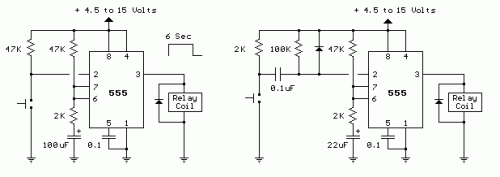
The following two circuits demonstrate the application of the 555 timer to activate a relay for a specified duration, achieved through pressing a momentary N/O push button. The circuit on the left is suitable for prolonged operation, allowing the button to be pressed and released while maintaining the timing period. For shorter intervals, a capacitor can be used to decouple the switch, ensuring that only the initial switch closure is perceived by the timer's input and that the switch can remain closed indefinitely without influencing the output.
In the inactive state, the output at pin 3 will be at ground and the relay will be disabled. The trigger input (pin 2) is held high by the 100K resistor and both capacitors are discharged. Upon pressing the button, the 0.1uF cap will charge through the button and the 100K resistor, causing a decrease in voltage at pin 2 for a brief period (approximately a few milliseconds). This falling voltage at pin 2 initiates the timing cycle within the 555. The output at pin 3 immediately rises to approximately near the supply voltage (around 10.4 volts for a 12 volt supply) and remains at that level until the 22 uF timing capacitor charges to roughly 2/3 of the supply voltage (approximately 1 second, as depicted). Many 12 volt relays operate effectively at 10.4 volts; therefore, if needed, the supply voltage can be increased to about 13.5 volts to compensate. The 555 output can supply up to 200mA of current, allowing for the replacement of the relay with a small lamp, doorbell, or other load requiring less than 200mA. When the button is released, the 0.1uF capacitor discharges through the 100K and 2K resistors. The diode across the 100K resistor prevents the voltage at pin 2 from exceeding the supply voltage during discharge. The 2K resistor in series with the 22uF cap limits the discharge current from pin 7 of the timer. This resistor may not be essential, but it’s advisable to restrict current when discharging capacitors across switch contacts or transistors.
