- Long Delay Timer Circuit: 35 Minute Battery-Powered Design
- Build Your Custom 3-9 Minute Beep Timer Circuit
- Build Your Amplifier Timer Circuit – 15 Minute Delay
- Timed Beeper Circuit: Build Your Precise Timer!
- Build Your 30-Minute Bedside Lamp Timer Circuit
- Time Delay Circuit: Build Your Appliance Protector
- Midnight Security Light Circuit: A 1:00 AM Intrusion Defense
- Delay Relay Circuit: 12V, 15s
- Build a Powerful 1300W Space Heater Circuit Diagram
- Building a 1-Second Delayed Pulse with the 555 Timer
- 555 Timer Mono Stable Circuit Design & Build Guide
- Build Precise Time Delays with a 12-Stage Binary Counter
- Time Delay Circuit: 5A Output from Low Voltage Batteries
- Build a Powerful 1300W AC Heater Circuit Design
- Build Your 9-Second LED Timer & Relay Circuit 9V
Build Your Custom 3-9 Minute Beep Timer Circuit
3V Battery Powered, Emits a Tone Following a Specified Duration
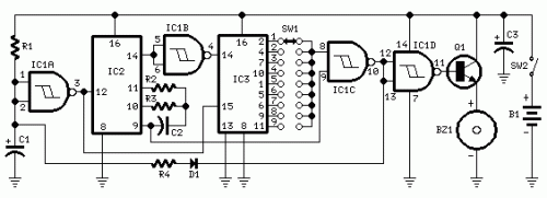
This circuit was developed in response to numerous requests from website visitors seeking a timer that produces a tone upon reaching a predetermined interval, ranging from one to nine minutes, primarily for exercise routines. As depicted within the circuit diagram, SW1 represents a 9-position rotary switch. Positioning the switch in the first location triggers the Piezo sounder to generate three brief sounds every minute. When set to the second location, the same phenomenon occurs after a two-minute pause, and so on, with the longest duration extending to nine minutes when the switch is in its final position.
Circuit Diagram:
Components:
- R1_____________47K 1/4W Resistor
- R2_____________10M 1/4W Resistor
- R3______________1M 1/4W Resistor
- R4_____________12K 1/4W Resistor (see annotations)
- C1,C3__________10µF 25V Electrolytic Capacitors
- C2____________100nF 63V Polyester Capacitor
- D1___________1N4148 75V 150mA Diode
- IC1____________4093 Quad 2-input Schmitt NAND Gate IC
- IC2____________4060 14-stage ripple counter and oscillator IC
- IC3____________4017 Decade counter with 10 decoded outputs IC
- Q1____________BC337 45V 800mA NPN Transistor
- SW1___________1-pole 9-way Rotary Switch (see annotations)
- SW2___________SPST Slider Switch
- BZ1___________Piezo sounder (incorporating 3KHz oscillator)
- B1____________3V Battery (two 1.5V AA or AAA cells in series etc.)
Annotations:
- Only a single instance of configuration is required; the rotary switch can be replaced by a permanently wired connection.
- A DIP-Switch may be used instead of the rotary type. Careful attention should be paid to ensure only one switch is active at a time, or the device could be harmed.
- Adjusting the value of R4 between 10K and 15K results in slightly varying durations of the short tones following the preset delay.
- To produce a one-second tone only after the set duration has elapsed, disconnect pin 9 of IC1C from pin 9 of IC2 and connect it to pin 8 of IC1C.
Integrated Circuits Details
The core of this timer circuit relies on several integrated circuits, each playing a distinct role in the timing and sound generation processes. The 4093 is a quad 2-input Schmitt NAND gate IC. This IC serves as a versatile building block, providing multiple independent Schmitt triggers to create complex timing patterns. Its Schmitt trigger functionality ensures that the output switches reliably between two states when the input signal crosses a specific threshold, contributing to the precise timing of the circuit. The 4060 is a 14-stage ripple counter and oscillator IC. This IC is commonly used to generate accurate time delays. The ripple counter stages sequentially toggle, producing a frequency that can be precisely controlled to deliver a specific delay period. The 4017 is a decade counter with 10 decoded outputs IC. This IC provides a decade-wide frequency counter, which is an essential element for timing applications. The 10-decoded outputs allow the counter to be configured for various timing intervals.
circuit from www.RedCircuits.com
