- Long Delay Timer Circuit: 35 Minute Battery-Powered Design
- Build Your Custom 3-9 Minute Beep Timer Circuit
- Build Your Amplifier Timer Circuit – 15 Minute Delay
- Timed Beeper Circuit: Build Your Precise Timer!
- Build Your 30-Minute Bedside Lamp Timer Circuit
- Time Delay Circuit: Build Your Appliance Protector
- Midnight Security Light Circuit: A 1:00 AM Intrusion Defense
- Delay Relay Circuit: 12V, 15s
- Build a Powerful 1300W Space Heater Circuit Diagram
- Building a 1-Second Delayed Pulse with the 555 Timer
- 555 Timer Mono Stable Circuit Design & Build Guide
- Build Precise Time Delays with a 12-Stage Binary Counter
- Time Delay Circuit: 5A Output from Low Voltage Batteries
- Build a Powerful 1300W AC Heater Circuit Design
- Build Your 9-Second LED Timer & Relay Circuit 9V
Timed Beeper Circuit: Build Your Precise Timer!
Description
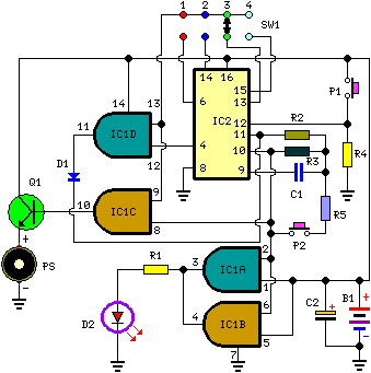
This circuit is intended for alerting purposes after a certain duration has passed. It is suitable for table games requiring a predetermined time to answer a question or to move a piece, or it serves as a modern alternative to the traditional hourglass. It is also beneficial for time management during children’s dental hygiene routines (at least two minutes!), or in the kitchen, and so on.
Circuit diagram:
Parts:
- R1 = 220Ω
- R2 = 10MΩ
- R3 = 1MΩ
- R4 = 10kΩ
- R5 = 47kΩ
- C1 = 100nF - 63V
- C2 = 22µF - 25V
- D1 = 1N4148
- D2 = 3mm, Red LED
- Q1 = BC337
- P1 = SPST Pushbutton (Start)
- P2 = SPST Pushbutton (Reset)
- PS = Piezo sounder (incorporating 3KHz oscillator)
- B1 = 3V Battery (2 AA 1.5V Cells in series)
- IC1 = CD4081 Quad 2 input AND Gate IC
- IC2 = CD4060 14 stage ripple counter and oscillator IC
- SW1 = 4 ways Switch (See notes)
Circuit operation:
Pushing on P1 initiates the oscillation of IC2, which is fixed by the values of R3 and C1. With these values specified, the oscillation frequency is approximately 4Hz. The LED D2, driven by IC1A and B, flashes at this same frequency, signaling proper circuit operation. SW1 selects the appropriate pin of IC2 to adjust the timing duration:
- Position 1 = 15 seconds
- Position 2 = 30 seconds
- Position 3 = 1 minute
- Position 4 = 2 minutes
When the selected pin of IC2 goes high, IC1C drives Q1 and the piezo sounder emits intermittent beeps at the same frequency as the LED. After about 7.5 seconds, pin 4 of IC2 goes high, and IC1D terminates the oscillator through D1. If premature termination is desired, pushing on P2 halts the counting process.
Notes:
- SW1 can be any type of switch with the desired number of positions. If a single fixed timing duration is needed, omit the switch and connect pins 9 and 13 of IC1 to the appropriate pin of IC2.
- The circuit's reset is not immediate. Pushing P2 forces IC2 to oscillate rapidly, but it takes a few seconds for the counting to complete, especially when a lengthy timer delay has been selected and the button is activated during the initial stages of the circuit’s startup. To accelerate the reset, consider reducing the value of R5, but be cautious: excessively low values can disrupt oscillation.
- Oscillation frequency varies depending on the manufacturer’s specifications for IC2. For example, Motorola ICs tend to operate at higher frequencies, necessitating adjustments to C1 and/or R3 values.
- The pins 1, 2, and 3 of IC2 can be utilized to obtain timing durations of 8, 16, and 32 minutes, respectively.
- An on-off switch is not included because the circuit consumes minimal current when in the off state.
Integrated Circuits in Detail
IC1: CD4081 Quad 2 input AND Gate IC
The CD4081 is a versatile quad AND gate integrated circuit. It consists of four independent AND gates, each with two inputs and one output. This IC is ideal for creating complex logic circuits and is frequently employed in digital electronics for switching and signal processing. It’s known for its reliability and ease of use in a wide range of applications, including this timing circuit’s operation, where it performs as a core component of the timing mechanism.
IC2: CD4060 14 stage ripple counter and oscillator IC
The CD4060 is a 14-stage ripple counter and oscillator IC. It is designed to generate a precise oscillating frequency and to count pulses. This particular IC is commonly used in timer circuits, frequency dividers, and various digital control applications. In this circuit, the CD4060 is crucial for generating the oscillating frequency that drives the LED and controls the timing duration, providing a reliable foundation for the timing function. Its ability to oscillate and count pulses makes it a vital element in this specific application.
