- Long Delay Timer Circuit: 35 Minute Battery-Powered Design
- Build Your Custom 3-9 Minute Beep Timer Circuit
- Build Your Amplifier Timer Circuit – 15 Minute Delay
- Timed Beeper Circuit: Build Your Precise Timer!
- Build Your 30-Minute Bedside Lamp Timer Circuit
- Time Delay Circuit: Build Your Appliance Protector
- Midnight Security Light Circuit: A 1:00 AM Intrusion Defense
- Delay Relay Circuit: 12V, 15s
- Build a Powerful 1300W Space Heater Circuit Diagram
- Building a 1-Second Delayed Pulse with the 555 Timer
- 555 Timer Mono Stable Circuit Design & Build Guide
- Build Precise Time Delays with a 12-Stage Binary Counter
- Time Delay Circuit: 5A Output from Low Voltage Batteries
- Build a Powerful 1300W AC Heater Circuit Design
- Build Your 9-Second LED Timer & Relay Circuit 9V
Build Your 30-Minute Bedside Lamp Timer Circuit
Description
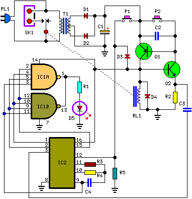
The objective of this circuit is to supply power to a lamp or other device for a specified duration – specifically, 30 minutes – followed by automatic deactivation. This design is particularly useful for nighttime reading, as it automatically extinguishes the bedside lamp once the reader falls asleep. Upon activation via pushbutton P1, the LED illuminates for approximately 25 minutes. Subsequently, it initiates a blinking sequence lasting for two minutes, pauses for another two minutes, and then resumes blinking for an additional two minutes just prior to the lamp’s final shutdown, signaling the end of the allotted operating time. Should the user desire to extend their reading time, they can gain an additional half-hour of illumination by pressing on P1. Turning off the lamp is achieved with ease by pressing on P2.
Circuit diagram:
Parts:
- R1 = 1K
- R2 = 4.7K
- R3 = 10M
- R4 = 1M
- R5 = 10K
- C1 = 470µF-25V
- C2-C4 = 100nF-63V
- C1 = 470µF-25V
- C2-C4 = 100nF-63V
- D1-D4 = 1N4002
- D5 = 5mm. Red LED
- IC1 = CD4012
- IC2 = CD4060
- Q1 = BC328
- Q2 = BC547
- P1,P2 = SPST Pushbuttons
- T1 = 9+9 Volt Secondary 1VA Mains transformer
- RL1 = 10.5V 470 Ohm Relay with SPDT 2A 220V switch
- PL1 = Male Mains plug
- SK1 = Female Mains socket
Circuit operation:
Q1 and Q2 form an ALL-ON ALL-OFF circuit which, in the inactive state, consumes very little current. Activation of pushbutton P1 initiates the circuit, engaging the relay and powering both ICs. The lamp is powered via the relay’s switch, and IC2 is reset with a positive voltage applied to pin 12. IC2 commences oscillating at a frequency determined by R4 and C4. After approximately 30 minutes, pin 3 transitions to a high state, resulting in the circuit’s termination via C3. During the preceding 6 minutes, the blinking action is active.
The LED performs a blinking action through connections to pins 1, 2, and 15 of IC2. The blinking frequency is supplied by IC2’s oscillator at pin 9. The two gates of IC1 are connected in parallel to provide increased current. A piezo sounder may be connected to pins 1 and 14 of IC1, if required. Timing adjustments can be achieved by modifying the values of C4 and/or R4.
