similar circuits
- Build Your 15-Second Courtesy Light Circuit Today
- Brightness Controller: Build a 1.5V LED/Lamp Circuit
- 12V DC Dimmer Circuit: Build Your Own Mood Lighting
- TRIAC Light Dimmer Circuit: Build Your 350W Dimmer
- Dome Lamp Dimmer Circuit: Build Your 700Hz Dimming System
- Build Your Automotive Lamp Dimmer: Circuit Diagram & Control
- Delayed Mains Lamp Circuit: Build Your 15-Second Timer
- 12 Volt Lamp Dimmer Circuit Diagram: Control Brightness with 555
- Sunrise Lamp Circuit: Build a 20-Minute Illumination Project
- 1.5 Hour Lamp Fader Sunset Lamp Circuit Diagram
- Build a 120V Lamp Dimmer: Full Wave Circuit Explained
- Build Your Inspiring 12 Volt Lamp Fader Circuit
- Illuminating Red Eyes
home :: led and light :: light dimmer :: build your automotive lamp dimmer: circuit diagram & control
Build Your Automotive Lamp Dimmer: Circuit Diagram & Control
Circuit Diagram
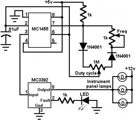
This schematic employs a MC3392 low-side guarded switch and an MC1455 timing circuit to create a vehicle-based instrument panel light regulation system. The luminance of incandescent bulbs can be adjusted by modulating the input to the MC3392. The modulating signal can be obtained directly from the MC1455 timer (or a digital processor). The MC1455 is arranged as a continuously running clock with adjustable frequency and pulse width control. The customary timer frequency is around 80 Hz when the frequency potentiometer is set to 1.0k. This frequency was selected to prevent any noticeable bulb shimmering. The pulse width potentiometer governs the pulse width over a range of roughly 3% to 97%. At 3%, the lamps are practically extinguished, and at 97%, the lamps are essentially completely illuminated. Numerous lamps can be managed, provided that the total current draw remains below 1 amp. An LED is utilized to indicate the presence of a system malfunction (excess voltage, current restriction, or thermal shutdown).More about components
The MC3392 is a versatile integrated circuit designed for protecting low-side switches in automotive and industrial applications. It provides overcurrent, overvoltage, and thermal protection, safeguarding connected circuits and components from damage. This IC typically incorporates a MOSFET, a comparator, and diagnostic circuitry within a single package, simplifying circuit design and reducing component count. It’s used to manage high currents without damaging the switch.Timing Circuit
The MC1455 is a classic 555 timer IC, frequently used as a timing circuit. In this system, it generates a precise clock signal to control the pulse width modulation (PWM) of the MC3392. This timer IC's frequency and duty cycle can be adjusted using potentiometers, allowing for fine-tuning of the lamp dimming characteristics. The output of the 555 timer drives the PWM signal, modulating the current flowing through the MC3392 and consequently, the brightness of the lamps. This IC is highly stable and provides precise timing signals for control applications.Security Warning: This circuit diagram is provided for informational purposes only. The author, John Smith, takes no responsibility for any damages or injuries resulting from the use or modification of this circuit. Users are advised to exercise caution and consult with a qualified professional before attempting to build or operate this circuit. Ensure adequate safety measures are in place, including proper grounding and protection against electrical shock. This circuit utilizes electronic components that can generate potentially hazardous voltages and currents.
Source: Electronics Database - Circuit Diagram Collection.
author: Motorola
circuit from http://www.electronics-lab.com/
circuit from http://www.electronics-lab.com/
