similar circuits
- Build Your 15-Second Courtesy Light Circuit Today
- Brightness Controller: Build a 1.5V LED/Lamp Circuit
- 12V DC Dimmer Circuit: Build Your Own Mood Lighting
- TRIAC Light Dimmer Circuit: Build Your 350W Dimmer
- Dome Lamp Dimmer Circuit: Build Your 700Hz Dimming System
- Build Your Automotive Lamp Dimmer: Circuit Diagram & Control
- Delayed Mains Lamp Circuit: Build Your 15-Second Timer
- 12 Volt Lamp Dimmer Circuit Diagram: Control Brightness with 555
- Sunrise Lamp Circuit: Build a 20-Minute Illumination Project
- 1.5 Hour Lamp Fader Sunset Lamp Circuit Diagram
- Build a 120V Lamp Dimmer: Full Wave Circuit Explained
- Build Your Inspiring 12 Volt Lamp Fader Circuit
- Illuminating Red Eyes
home :: led and light :: light dimmer :: 12 volt lamp dimmer circuit diagram: control brightness with 555
12 Volt Lamp Dimmer Circuit Diagram: Control Brightness with 555
Description
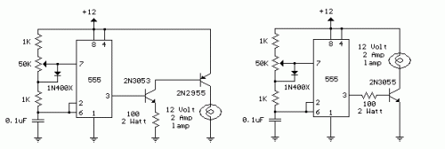
A 12 volt / 2 amp lamp controller is presented here, suitable for adjusting the brightness of a standard 25 watt car indicator or rear light by modulating the timing of a 555 timer oscillator operating in astable mode. Adjusting the position of the potentiometer’s wiper results in a rapid charging of the capacitor via the 1K resistors and the diode, creating a brief positive period alongside a prolonged negative period, which reduces the lamp’s brightness considerably. Conversely, moving the wiper to its lowest setting causes the capacitor to charge primarily through the 1K resistors and the 50K potentiometer, alongside discharging via the lower 1K resistor, generating a lengthy positive pulse and a short negative pulse, effectively maximizing the lamp’s luminosity. The output of the 200 Hz square wave can be modified to range from approximately 5% to 95%. The two circuits detailed below demonstrate how to connect the lamp to either the positive or negative rail of the power supply.Circuit diagram
circuit from http://www.bowdenshobbycircuits.info/
