- Build Your 15-Second Courtesy Light Circuit Today
- Brightness Controller: Build a 1.5V LED/Lamp Circuit
- 12V DC Dimmer Circuit: Build Your Own Mood Lighting
- TRIAC Light Dimmer Circuit: Build Your 350W Dimmer
- Dome Lamp Dimmer Circuit: Build Your 700Hz Dimming System
- Build Your Automotive Lamp Dimmer: Circuit Diagram & Control
- Delayed Mains Lamp Circuit: Build Your 15-Second Timer
- 12 Volt Lamp Dimmer Circuit Diagram: Control Brightness with 555
- Sunrise Lamp Circuit: Build a 20-Minute Illumination Project
- 1.5 Hour Lamp Fader Sunset Lamp Circuit Diagram
- Build a 120V Lamp Dimmer: Full Wave Circuit Explained
- Build Your Inspiring 12 Volt Lamp Fader Circuit
- Illuminating Red Eyes
TRIAC Light Dimmer Circuit: Build Your 350W Dimmer
Description
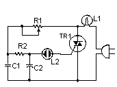
This compact circuit is suitable for controlling illumination, capable of reducing light output up to approximately 350 watts. It employs a straightforward, conventional TRIAC configuration, which, according to my observations, produces minimal thermal generation. It's important to acknowledge that this design is not compatible with the operation of fluorescent lighting.
Circuit Diagram
Components
- R1 50K Potentiometer
- R2 15K 1/2W Resistor
- C1, C2 0.068 250V Capacitor
- L1 Lamp To Be Controlled (maximum 350 watts)
- L2 Neon Lamp
- TR1 40502 TRIAC
- VARIOUS Case, Knob, Heatsink For TR1, Wire, Socket For L1
Notes
- This circuit is specifically designed for operation with 117VAC power. Utilizing 220 or 240 VAC will result in irreversible damage to the circuit. The maximum rated load for L1 is 350 watts.
- The circuit’s safe and proper operation requires installation within a protective enclosure.
Integrated Circuit Details
The core component of this circuit is the 40502 TRIAC (Triode for Alternating Current). This integrated circuit is a three-terminal semiconductor device designed for controlling AC power. It acts as an electronically controlled switch, allowing current to flow through a circuit when triggered by a small gate current. The 40502 is a commonly used, general-purpose TRIAC that’s reliable and has a high switching speed. It’s typically employed in light dimmers and other AC power control applications. Its operation is based on a lightly doped silicon junction, and it's rated for typical AC voltages and currents. Its gate terminal is used to initiate conduction, and once conduction begins, the TRIAC remains conducting until the current drops below a certain threshold. The 40502 is available in various packages suitable for surface mounting or through-hole applications.
