- Build Your 15-Second Courtesy Light Circuit Today
- Brightness Controller: Build a 1.5V LED/Lamp Circuit
- 12V DC Dimmer Circuit: Build Your Own Mood Lighting
- TRIAC Light Dimmer Circuit: Build Your 350W Dimmer
- Dome Lamp Dimmer Circuit: Build Your 700Hz Dimming System
- Build Your Automotive Lamp Dimmer: Circuit Diagram & Control
- Delayed Mains Lamp Circuit: Build Your 15-Second Timer
- 12 Volt Lamp Dimmer Circuit Diagram: Control Brightness with 555
- Sunrise Lamp Circuit: Build a 20-Minute Illumination Project
- 1.5 Hour Lamp Fader Sunset Lamp Circuit Diagram
- Build a 120V Lamp Dimmer: Full Wave Circuit Explained
- Build Your Inspiring 12 Volt Lamp Fader Circuit
- Illuminating Red Eyes
Brightness Controller: Build a 1.5V LED/Lamp Circuit
Description
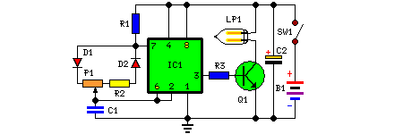
This apparatus was created according to a specific request; its purpose is to regulate the brightness of four incandescent lamps (a ring light) powered by two AA or AAA batteries, facilitating close-up photography with a digital camera. Naturally, it can be utilized in diverse applications, as desired. IC1 generates a 150Hz square wave featuring a configurable duty cycle. When the cursor of P1 is fully moved towards D1, the resulting positive pulses at pin 3 of IC1 are exceedingly narrow.
Bulb LP1, driven by Q1, remains switched off, due to insufficient voltage across its terminals. However, when the cursor of P1 is rotated towards R2, the output pulses widen, attaining their greatest amplitude when the potentiometer is adjusted fully clockwise. Consequently, the bulb achieves its maximum illumination.
Circuit diagram:
Parts:
- P1 = 470K
- R1 = 10K
- R2 = 47K
- R3 = 1.5K
- C1 = 22nF-63V
- C2 = 100uF-25V
- D1 = 1N4148
- D2 = 1N4148
- Q1 = BD681
- B1 = 2xAA cells connected in series
- IC1 = 7555 or TS555CN
- LP1 = 1.5V 200mA Bulb
- SW1 = SPST Switch
Notes:
- LP1 may consist of one or multiple 1.5V bulbs connected in parallel. The maximum permissible total output current is approximately 1A.
- R2 controls the output voltage, measured across LP1 terminals, limiting it to 1.5V. Its actual value is dependent on the total current drawn by the bulb(s) and should be set at full load to achieve approximately 1.5V across the bulb(s) terminals when P1 is rotated fully clockwise.
More about components
IC1, identified as 7555 or TS555CN, is a versatile 555 timer IC. This integrated circuit functions as a timing pulse generator. The 555 timer IC is widely used in various applications, including pulse generation, oscillator circuits, and timing circuits. Its core function is to produce a series of pulses with a controlled frequency and duty cycle. The IC’s operation is typically controlled by connecting it to external resistors and capacitors to define the desired timing parameters. Pin 3 provides the output pulses, which are generated based on the timer’s internal circuitry. The 555 timer is a fundamental component in electronic design, offering flexibility in generating precise timing signals.
