similar circuits
- Build Your 15-Second Courtesy Light Circuit Today
- Brightness Controller: Build a 1.5V LED/Lamp Circuit
- 12V DC Dimmer Circuit: Build Your Own Mood Lighting
- TRIAC Light Dimmer Circuit: Build Your 350W Dimmer
- Dome Lamp Dimmer Circuit: Build Your 700Hz Dimming System
- Build Your Automotive Lamp Dimmer: Circuit Diagram & Control
- Delayed Mains Lamp Circuit: Build Your 15-Second Timer
- 12 Volt Lamp Dimmer Circuit Diagram: Control Brightness with 555
- Sunrise Lamp Circuit: Build a 20-Minute Illumination Project
- 1.5 Hour Lamp Fader Sunset Lamp Circuit Diagram
- Build a 120V Lamp Dimmer: Full Wave Circuit Explained
- Build Your Inspiring 12 Volt Lamp Fader Circuit
- Illuminating Red Eyes
Build a 120V Lamp Dimmer: Full Wave Circuit Explained
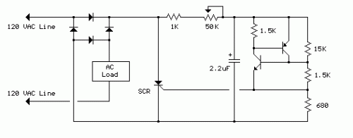
Circuit diagram
The complete wave phase-control circuit presented below originated from an RCA power circuits publication dated 1969. The load is connected in series with the alternating current source and the four diodes deliver a full-wave rectified voltage to the anodes of silicon-controlled rectifiers (SCRs). Two diminutive signal transistors are arranged in a switching configuration such that when the voltage across the 2.2µF capacitor reaches approximately 8 volts, the transistors will activate and discharge the capacitor through the SCR gate, initiating its conduction. The delay from the commencement of each half-cycle until the SCR begins to conduct is regulated by the 50kΩ resistor, which determines the required duration for the 2µF capacitor to charge to 8 volts. Reducing the resistance shortens the delay, causing the SCR to conduct earlier within each half-cycle and thereby applying a higher average voltage across the load. Setting the resistance to its minimum value allows the SCR to trigger when the voltage rises to around 40 volts or 15 degrees into the cycle. To account for component variations, the 15kΩ resistor can be modified slightly to ensure that the output voltage is near zero when the 50kΩ potentiometer is set to maximum. Increasing the 15kΩ resistor will diminish the adjustment range of the 50kΩ pot for minimal output and conversely. Exercise caution and avoid direct contact with the circuit while it is connected to the AC line.More about components
Silicon-controlled rectifiers (SCRs) are solid-state semiconductor devices that act as switches when controlled by a gate signal. They are commonly utilized in switching power supplies and other applications requiring controlled switching of DC current. They are characterized by their ability to conduct current in only one direction when triggered, offering a controlled method to switch high-power circuits.The use of integrated circuits in this circuit provides a compact and reliable switching mechanism. The SCRs, combined with the transistors, offer precise control over the conduction of the load, optimizing the overall performance of the phase-controlled circuit. The inherent stability and reduced component count provided by the ICs contribute to the circuit's robustness and ease of maintenance. These circuits represent a fundamental building block in power electronics, offering efficient and adaptable solutions for a wide range of applications.
circuit from http://www.bowdenshobbycircuits.info/
