- Long Delay Timer Circuit: 35 Minute Battery-Powered Design
- Build Your Custom 3-9 Minute Beep Timer Circuit
- Build Your Amplifier Timer Circuit – 15 Minute Delay
- Timed Beeper Circuit: Build Your Precise Timer!
- Build Your 30-Minute Bedside Lamp Timer Circuit
- Time Delay Circuit: Build Your Appliance Protector
- Midnight Security Light Circuit: A 1:00 AM Intrusion Defense
- Delay Relay Circuit: 12V, 15s
- Build a Powerful 1300W Space Heater Circuit Diagram
- Building a 1-Second Delayed Pulse with the 555 Timer
- 555 Timer Mono Stable Circuit Design & Build Guide
- Build Precise Time Delays with a 12-Stage Binary Counter
- Time Delay Circuit: 5A Output from Low Voltage Batteries
- Build a Powerful 1300W AC Heater Circuit Design
- Build Your 9-Second LED Timer & Relay Circuit 9V
Build Your Precise 9-Minute Jogging Timer Circuit Diagram
3V Battery operated
Emits a tone following a predetermined duration, such as one, two, or three minutes, for exercise applications.
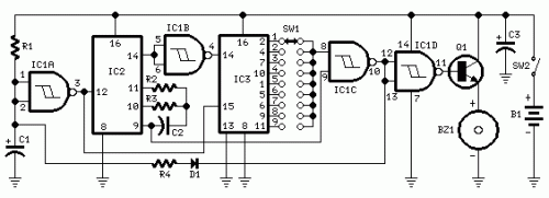
Circuit Diagram
Components:
- R1 47K 1/4W Resistor
- R2 10M 1/4W Resistor
- R3 1M 1/4W Resistor
- R4 12K 1/4W Resistor (refer to accompanying documentation)
- C1, C3 10µF 25V Electrolytic Capacitors
- C2 100nF 63V Polyester Capacitor
- D1 1N4148 75V 150mA Diode
- IC1 4093 Quad 2 input Schmitt NAND Gate IC
- IC2 4060 14 stage ripple counter and oscillator IC
- IC3 4017 Decade counter with 10 decoded outputs IC
- Q1 BC337 45V 800mA NPN Transistor
- SW1 1 pole 9 ways Rotary Switch (see supplemental information)
- SW2 SPST Slider Switch
- BZ1 Piezo sounder (containing a 3KHz oscillator)
- B1 3V Battery (two 1.5V AA or AAA cells connected in series or similar)
Device Objective:
This circuit was developed in response to repeated requests from website visitors for a timing device that would produce a sound signal after a specific period – for instance, one, two, or three minutes – intended for use during physical activity.
As depicted in the Circuit Diagram, SW1 is a 9-way, single-pole rotary switch. When configured in position 1, the Piezo sounder generates three brief pulses each minute. In position 2, the same outcome occurs after two minutes, and so on, extending to a maximum interval of nine minutes when positioned in position 9.
Supplemental Information:
- For single setup applications, the rotary switch can be replaced with a permanently wired connection.
- A DIP-Switch can be substituted for the rotary type. Caution must be exercised to ensure only one switch is active at any given time, otherwise the device could be damaged.
- Adjusting R4 between 10K and 15K will result in a different number of short pulses following the programmed time delay.
- To achieve a one-second pulse output after the preset duration, disconnect pin 9 of IC1C from pin 9 of IC2 and connect it to pin 8 of IC1C.
Integrated Circuit Descriptions:
IC1 (4093): This is a quad 2-input Schmitt NAND gate IC. It is commonly used in digital circuits for creating latching or switching functionality. It features four independent NAND gates, each with two inputs and one output. This IC is widely used in timer circuits, level-shift circuits, and various other digital logic applications. Its Schmitt trigger input provides noise immunity and stable switching behavior. The 4093 IC's advantages include its high input impedance, low power consumption, and relatively small size.
IC2 (4060): The 4060 is a 14-stage ripple counter and oscillator IC. It’s a versatile component often employed in timing circuits and frequency generation. It utilizes a cascading series of flip-flops to count clock pulses, producing an output frequency that varies with the count. This IC is commonly used in digital clocks, frequency dividers, and other applications requiring precise timing or frequency control. The 4060’s key characteristics are its stability, accuracy, and ease of use in timing applications. It typically operates at frequencies from a few Hz to several MHz, depending on the design and component values used.
IC3 (4017): The 4017 is a decade counter with 10 decoded outputs IC. It's a widely utilized counter IC, particularly for decimal-based counting applications. This IC contains ten cascaded flip-flops, generating an output signal that changes state every tenth clock pulse. The 4017 is frequently found in digital displays, frequency dividers, and other applications where a sequential counting action is needed. The 4017’s advantages include its high reliability, low cost, and simple programming scheme. It is a popular choice for both beginners and experienced electronics enthusiasts.
circuit from http://www.redcircuits.com/
