- Long Delay Timer Circuit: 35 Minute Battery-Powered Design
- Build Your Custom 3-9 Minute Beep Timer Circuit
- Build Your Amplifier Timer Circuit – 15 Minute Delay
- Timed Beeper Circuit: Build Your Precise Timer!
- Build Your 30-Minute Bedside Lamp Timer Circuit
- Time Delay Circuit: Build Your Appliance Protector
- Midnight Security Light Circuit: A 1:00 AM Intrusion Defense
- Delay Relay Circuit: 12V, 15s
- Build a Powerful 1300W Space Heater Circuit Diagram
- Building a 1-Second Delayed Pulse with the 555 Timer
- 555 Timer Mono Stable Circuit Design & Build Guide
- Build Precise Time Delays with a 12-Stage Binary Counter
- Time Delay Circuit: 5A Output from Low Voltage Batteries
- Build a Powerful 1300W AC Heater Circuit Design
- Build Your 9-Second LED Timer & Relay Circuit 9V
Astable Timer Circuit Diagram: Light-Sensitive Timing
Description
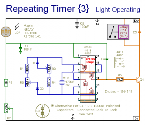
This circuit closely resembles Repeating Timer No.2. However, the inclusion of the light-dependent resistor allows the operation of this timer to be restricted to daylight hours. R7 facilitates the setting of the light level at which the timer ceases its function. The specific type of LDR is not crucial; the voltage on pin 1 is the primary consideration. Any LDR should perform satisfactorily, though adjustments to the value of R7 may be necessary to achieve the desired range of adjustment.
Light Dependent Resistor (LDR)
The Light Dependent Resistor, or LDR, is a semiconductor device whose resistance decreases with increasing incident light intensity. It’s a crucial component in this circuit, enabling the timer to respond to changes in ambient light. Because LDRs are highly variable in their characteristics, it’s important to experiment with different values of R7 to fine-tune the timer’s operation for optimal results. This component is vital in creating a light-sensitive time circuit.
Schematic Diagram
Setting The Timer
Fundamentally, this circuit operates as an Astable Oscillator. The output durations are governed by the value of C1, and the rate at which it charges and discharges through the resistor network. The duration the relay remains energized is controlled by R1 & R2, while the duration it remains de-energized is controlled by R3 & R4. The fixed resistors establish the minimum and maximum period lengths, with the maximum period lengths determined by R2 & R3. With the provided component values, both periods are adjustable, typically ranging from approximately 1 to 30 minutes.
Component values can be modified to suit specific requirements. If precise time periods aren’t essential, and approximate durations are sufficient, the potentiometers can be omitted, relying solely on R1 & R4 to set the times. Due to manufacturing variances, the precise duration of the periods available is dependent on the attributes of the actual components utilized – a 4093 will deliver longer time intervals compared to a 4011.
IMPORTANT
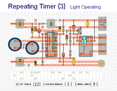
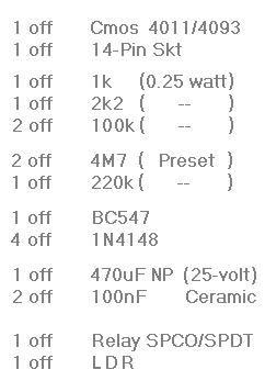
Do not employ the "on-board" relay to switch mains voltage. The board's layout lacks adequate isolation between the relay contacts and the low-voltage components. If you require switching of mains voltage, mount a suitably rated relay in a safe location – Away From The Board. I’ve utilized a SPCO/SPDT relay, but a multi-pole relay can be employed if it aligns with your application.
Alternative Capacitor
During operation, the capacitor C1 exhibits a reversing charge polarity. Consequently, C1 must be non-polarised. However, a non-polarised simulation can be achieved by connecting two polarised 1000uF capacitors in reverse polarity, as demonstrated. The rationale and methodology behind this approach are detailed in the Comprehensive Circuit Description. Because non-polarised capacitors are not consistently available, the prototype was constructed utilizing two polarised capacitors.
Veroboard Layout
This timer is designed for a 12-volt power supply. Nonetheless, it will function across a range of 5 to 15 volts. The key is to select a relay with a coil voltage that is appropriate for your power supply.


