- Long Delay Timer Circuit: 35 Minute Battery-Powered Design
- Build Your Custom 3-9 Minute Beep Timer Circuit
- Build Your Amplifier Timer Circuit – 15 Minute Delay
- Timed Beeper Circuit: Build Your Precise Timer!
- Build Your 30-Minute Bedside Lamp Timer Circuit
- Time Delay Circuit: Build Your Appliance Protector
- Midnight Security Light Circuit: A 1:00 AM Intrusion Defense
- Delay Relay Circuit: 12V, 15s
- Build a Powerful 1300W Space Heater Circuit Diagram
- Building a 1-Second Delayed Pulse with the 555 Timer
- 555 Timer Mono Stable Circuit Design & Build Guide
- Build Precise Time Delays with a 12-Stage Binary Counter
- Time Delay Circuit: 5A Output from Low Voltage Batteries
- Build a Powerful 1300W AC Heater Circuit Design
- Build Your 9-Second LED Timer & Relay Circuit 9V
Repeating Timer No4: Build Your Dark-Activated Circuit
Description
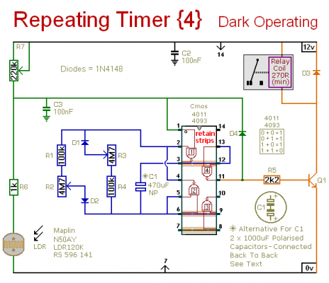
This circuit closely resembles Repeating Timer No.2. Nevertheless - the inclusion of the light-dependent resistor enables the operation of this timer to be limited to periods of darkness. R7 allows you to define the level of darkness at which the timer will initiate. The specific type of LDR isn't crucial; the critical factor is the voltage on pin 1. Any LDR should perform satisfactorily provided this voltage is correct. However - you may need to adjust the value of R7 to achieve the desired range of adjustment.
Light Dependent Resistor
Light-dependent resistors, often called LDRs, are variable resistors whose resistance decreases when exposed to light. They are commonly used in circuits to detect changes in ambient light levels. The resistance of an LDR is highly dependent on the amount of light shining on it. A higher light intensity results in a lower resistance, and vice versa. Because of this sensitivity, they are frequently incorporated into circuits to create light-sensitive timers, sensors, and other applications. The exact behavior of an LDR depends on its specific characteristics and the conditions of illumination.
Schematic Diagram
Setting The Timer
The circuit functions as an Astable Oscillator. The output durations depend on the value of C1 - and the rate at which it charges and discharges through the resistor network. The duration that the relay remains energized is controlled by R1 & R2. Simultaneously - the duration that it remains de-energized is controlled by R3 & R4. The fixed resistors establish the minimum and maximum period lengths - and the maximum period lengths are set by R2 & R3. With the specified component values - both periods are adjustable from approximately 1 to 30 minutes.
You can modify the component values to match your particular needs. If your time periods don’t require high precision - and approximate values are sufficient - you can eliminate the potentiometers altogether - and solely rely on R1 & R4 to set the times. Due to manufacturing variations - the precise lengths of the time periods available depend on the characteristics of the actual components utilized - and a 4093 will yield longer time periods than a 4011.
IMPORTANT
Do not utilize the “on-board” relay to switch mains voltage. The board’s design lacks adequate isolation between the relay contacts and the low-voltage components. If you need to switch mains voltage - mount a suitably rated relay in a safe location - Away From The Board. I've employed a SPCO/SPDT relay - but you can use a multi-pole relay if it suits your application.
Alternative Capacitor
While the oscillator is operating - the polarity of the charge on C1 reverses repeatedly. Therefore - C1 needs to be non-polarized. However - you can mimic a non-polarized 470uF capacitor by connecting two 1000uF polarized capacitors in reverse polarity, as shown. The explanation of how and why this works can be found in the Detailed Circuit Description. Because non-polarized capacitors aren’t always readily available - the prototype was constructed using two polarized capacitors.
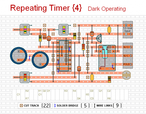
Veroboard Layout
The timer is designed for a 12-volt power supply. Nevertheless - it will operate at voltages ranging from 5 to 15 volts. All you require is to select a relay with a coil voltage that corresponds to your supply.


