- Long Delay Timer Circuit: 35 Minute Battery-Powered Design
- Build Your Custom 3-9 Minute Beep Timer Circuit
- Build Your Amplifier Timer Circuit – 15 Minute Delay
- Timed Beeper Circuit: Build Your Precise Timer!
- Build Your 30-Minute Bedside Lamp Timer Circuit
- Time Delay Circuit: Build Your Appliance Protector
- Midnight Security Light Circuit: A 1:00 AM Intrusion Defense
- Delay Relay Circuit: 12V, 15s
- Build a Powerful 1300W Space Heater Circuit Diagram
- Building a 1-Second Delayed Pulse with the 555 Timer
- 555 Timer Mono Stable Circuit Design & Build Guide
- Build Precise Time Delays with a 12-Stage Binary Counter
- Time Delay Circuit: 5A Output from Low Voltage Batteries
- Build a Powerful 1300W AC Heater Circuit Design
- Build Your 9-Second LED Timer & Relay Circuit 9V
Build Your 100uF Photo Timer Circuit – Precise Timing!
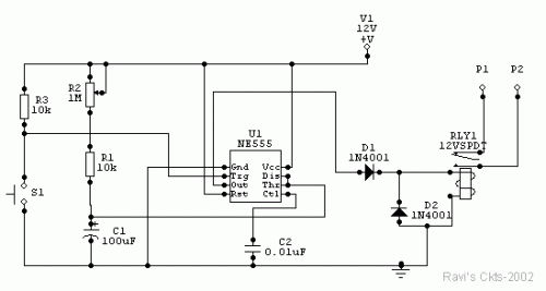
Circuit Diagram
The timing is determined by a potentiometer, R2, offering a range from 1 second to 100 seconds. This is achieved through a timing capacitor, C1, valued at 100uF. The output signal at pin 3 is typically low, maintaining the relay in an inactive state. Activating the momentary push switch, S1, energizes the relay, holding it closed for a duration of 1.1 times (R1 + R2). Following this, the capacitor, C1, is released, and the relay returns to its de-energized condition. The precise length of the timing period will vary depending on the actual capacitance of the capacitor C1. Most electrolytic capacitors are specified with a minimum guaranteed value, and the actual value may exceed this rating. It is advisable to calibrate the circuit for different potentiometer knob positions after the timing capacitor has undergone a period of aging. Once the capacitor has stabilized, the provided timings should adequately meet photographic requirements.
Components
- C1 - 100uF, 25V electrolytic
- C2 - 0.01uF, disc ceramic
- D1, D2 - DR50 or 1N4001
- R1, R2 - 10K ohms, ¼ watts
- R3 - 1 M ohms, potentiometer
- RLY1 - 12V, DC relay, operating current less than 200mA
- S1 - Push-to-on switch
- U1 - NE555 timer IC
- P1 & P2 are for exposure lamp circuit.
NE555 Timer IC
The NE555 is a versatile integrated circuit widely used as a timing circuit. This specific application utilizes the NE555 as a core component within the timing circuit, facilitating the generation of the desired timing intervals. The NE555, with its inherent ability to create accurate time delays, is crucial for the operation of the circuit. The IC functions by generating a predictable output pulse, allowing for precise control of the timing interval. It’s a common choice for these applications because of its readily available supply voltages and ease of use. It is typically operated with a supply voltage of 5V to 15V, and offers precise timing capabilities based on its internal circuitry.
circuit from http://www.electronics-lab.com/
